
Reciprocating rotary CVD equipment and application method

Pending Publication Date: 2022-01-27
BETONE TECH SHANGHAI
View PDF0 Cites 0 Cited by
  • Summary
  • Abstract
  • Description
  • Claims
  • Application Information

AI Technical Summary

Benefits of technology

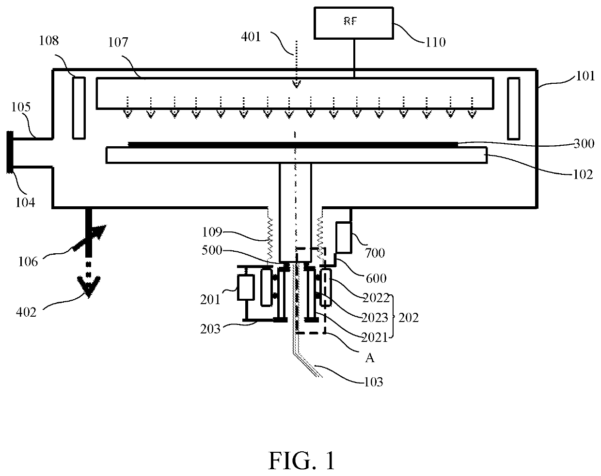
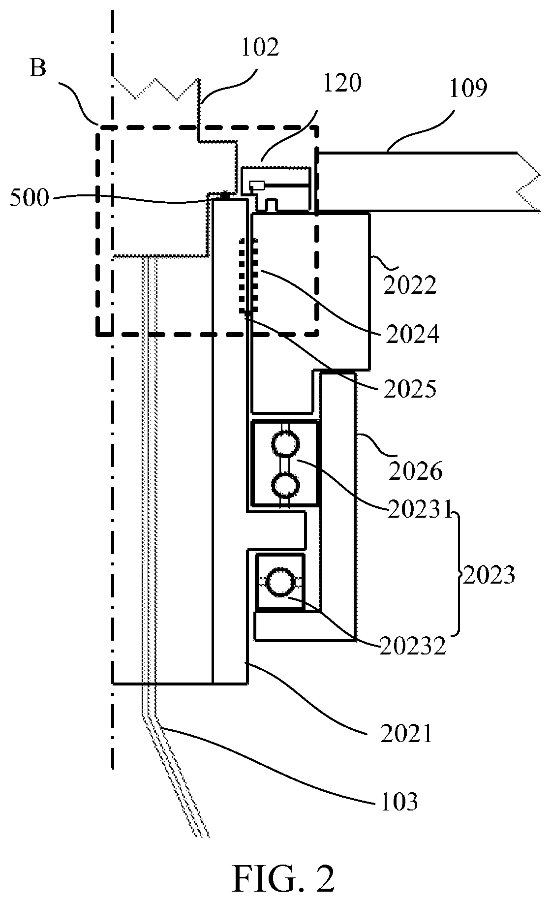
The present invention provides a reciprocating rotary CVD apparatus and a method for applying it. The apparatus includes a rotating apparatus that rotates to improve the uniformity of thin film deposition on a wafer. The wafer is rotated in a reciprocating manner within an optimal angle range to achieve the optimal thin film deposition uniformity. The reciprocating rotation angle is limited to be not more than 360 degrees to avoid problems of electrical connection and cooling channel connection during rotation. The apparatus simplifies the design, mounting, debugging, and manufacturing of the reaction cavity, improves the thin film deposition uniformity and reduces the apparatus and wafer manufacturing costs. Overall, the reciprocating rotary CVD apparatus and method consistent with the present invention provide improved thin film deposition with good uniformity on the wafer surface.

Problems solved by technology

To adapt to constant pursuits of a high-quality, high-efficiency, low-cost, and large-size wafer (for example, a size of the wafer is 300 mm) process in the current semiconductor industry, it is particularly important to improve the uniformity of a CVD thin film deposited on the wafer, and a process of obtaining a high-quality deposited thin film with good uniformity is relatively complex.
The non-uniformity of distribution of parameters in the reaction cavity causes undesirable phenomena of non-uniform thickness, non-uniform components, non-uniform physical properties, and the like on the thin film deposited on the surface of the wafer.
Consequently, various states in the reaction cavity are not consistent, including design, for example, a transfer channel of the wafer is on a local position of a cavity and gas exhaust channels are non-uniformly distributed on the cavity, manufacturing, and assembly, for example, centers of various components in the reaction cavity cannot be perfectly aligned during actual equipment assembly.
However, such connection manners lead to a complex apparatus structure, increase apparatus costs, and bring new problems such as low electrical connection reliability and low temperature measurement accuracy.
For example, the electrical contact may become unreliable along with the wear / oxidation of a contact surface, a contact resistance may be changed along with a magnitude of a spring contact force, and electrical shielding may not be well performed to generate / receive an interference signal.
As an electrode, the wafer heating base needs to satisfy reliable grounding for high frequency and high power radio frequency, so that if the wafer heating base is connected in a sliding connection manner, adverse impact is caused to the reliable electrical connection required by a radio frequency system.
However, because the heater is not wrapped in the base, the heater is inevitably exposed to various chemical reactive gases during thin film deposition in the cavity and a cleaning gas used for cleaning the cavity, and these corrosive gases are very disadvantageous to the life time of the heater.
As a result, the time of the entire adjustment process is increased, and the speed of thin film deposition is affected.
Because the temperature of the base needs to be measured, if the thermocouple is placed on the base, the thermocouple wire is wound due to rotation of the base, and if thet thermocouple is not in direct contact with the base, the wire is not wound but there is a new problem of the accuracy of temperature measurement.

Method used


Image

  • Reciprocating rotary CVD equipment and application method
  • Reciprocating rotary CVD equipment and application method
  • Reciprocating rotary CVD equipment and application method

Examples


Embodiment Construction

[0037]The following describes implementations of the present invention by using specific embodiments. A person skilled in the art may easily understand other advantages and effects of the present invention from the content disclosed in this specification. The present invention may also be implemented or applied through other different specific implementations. Various details in this specification may also be modified or changed based on different viewpoints and applications without departing from the spirit of the present invention. For example, during detailed description of the embodiments of the present invention, for ease of description, a cross-sectional view representing a apparatus structure is not enlarged partially according to a general proportion, and the schematic diagram is merely an example, which should not limit the protection scope of the present invention herein. In addition, the three-dimensional space dimensions of a length, a width, and a depth should be compri...


PUM

PropertyMeasurementUnit
Angleaaaaaaaaaa
Angleaaaaaaaaaa
Widthaaaaaaaaaa

Abstract

A reciprocating rotary CVD apparatus and a method for applying same. The reciprocating rotary CVD apparatus includes a cavity, a wafer heating base, a rotating apparatus. The rotating apparatus is located outside the cavity and includes a rotating power mechanism and a rotating sealing mechanism, and the rotating sealing mechanism includes a rotating member and a fixed member; the fixed member is fixedly and hermetically connected to the cavity, the rotating member is fixedly and hermetically connected to the wafer heating base, the rotating member is movably and hermetically connected to the fixed member, and the rotating member is connected to the rotating power mechanism, to drive, by using the rotating power mechanism, the rotating member and the wafer heating base to perform reciprocating rotation. In the present invention, the rotating apparatus rotates, to improve the uniformity of thin film deposition in a circumferential direction of a wafer.

Description

CROSS REFERENCE TO RELATED APPLICATION[0001]The present application claims the benefit of priority to Chinese Patent Application No. CN 2020104585359, entitled “RECIPROCATING ROTARY CVD APPARATUS AND METHOD FOR APPLYING SAME”, filed with CNIPA on May 27, 2020, the disclosure of which is incorporated herein by reference in its entirety for all purposes.BACKGROUND OF THE PRESENT INVENTIONField of Invention[0002]The present invention belongs to the field of chemical vapor deposition technologies and semiconductor apparatus manufacturing, and specifically relates to a reciprocating rotary chemical vapor deposition (CVD) apparatus and a method for applying same.Description of Related Arts[0003]Chemical vapor deposition (CVD) is a technology widely used in a semiconductor industry and used for depositing a thin film, and a CVD apparatus includes a reaction cavity and a wafer heating base. When two or more gaseous raw materials are introduced into the reaction cavity, the gaseous raw mater...

Claims


Application Information

Patent Timeline
IPC IPC(8): C23C16/458C23C16/505
CPCC23C16/4584C23C16/505C23C16/4586C23C16/4581C23C16/52C23C16/4408C23C16/463C23C16/4409
Inventor JIN, XIAOLIANGSUNG, WALEYWEITSUNGLI, ZHONGYUN
Owner BETONE TECH SHANGHAI
Learn More