
Extruders and printing machines for 3D metal printing

a printing machine and metal technology, applied in the field of three-dimensional printing, can solve the problems of not being able to handle metallic filaments, available 3d printers are not configured to utilize printing materials, etc., and achieve the effect of achieving desirable feed efficiency and adequate friction for

Active Publication Date: 2022-01-06
3DGENCE AMERICA INC
View PDF3 Cites 0 Cited by
  • Summary
  • Abstract
  • Description
  • Claims
  • Application Information

AI Technical Summary

Benefits of technology

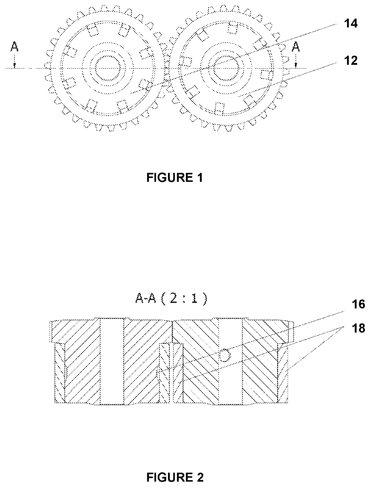
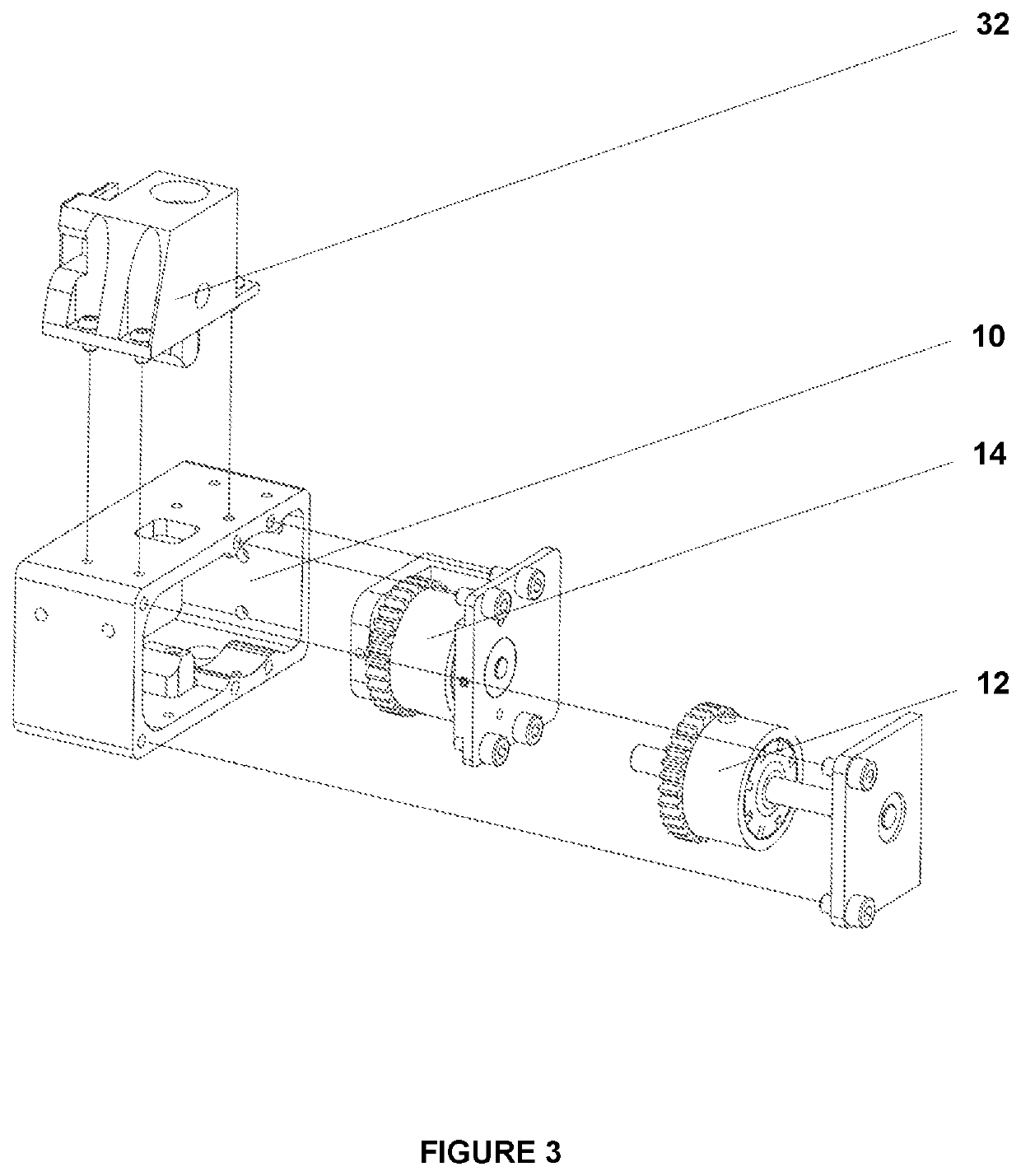
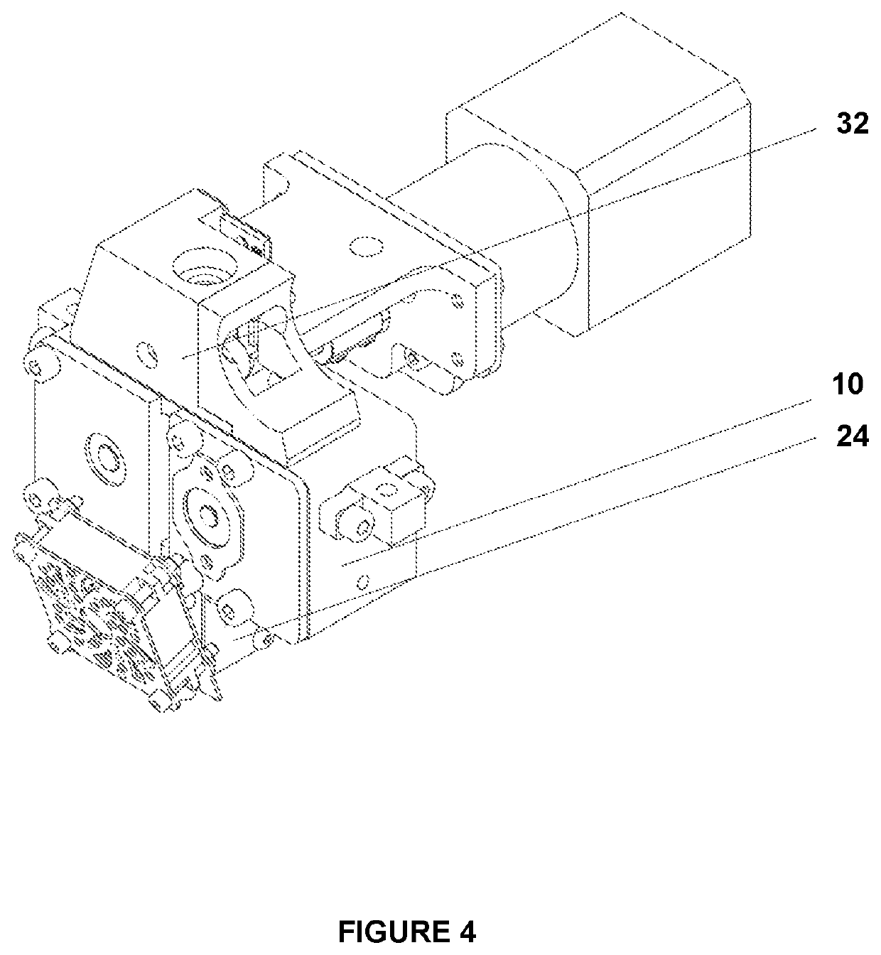
The present invention provides 3D printing extruders and machines that are particularly adapted for printing with metallic filaments. These extruders have two rotating elements that make contact with the metal filament and are covered with a flexible coating to enable them to grip and advance the filament forward towards the print head. The extruders can be easily installed in existing 3D printing machines without specialized tools and are designed to be compatible with existing machines. The extruders have a material feed zone that is covered with a resilient and flexible coating, which provides adequate friction for the metal printing materials. The invention also provides methods of printing target objects using the extruders and printers.

Problems solved by technology

Notably, however, currently-available 3D printers are not configured to utilize a printing material (substrate) that consists of metal in the form of a filament (or that otherwise includes a high level of metal in a filament).
Such currently-available 3D printers are not configured to handle metallic filaments, due to the fragility of such material, low feed rates, uneven material flows, and high risk of print failures.

Method used


Image

  • Extruders and printing machines for 3D metal printing
  • Extruders and printing machines for 3D metal printing
  • Extruders and printing machines for 3D metal printing

Examples


Embodiment Construction

[0018]The following will describe, in detail, several preferred embodiments of the present invention. These embodiments are provided by way of explanation only, and thus, should not unduly restrict the scope of the invention. In fact, those of ordinary skill in the art will appreciate upon reading the present specification and viewing the present drawings that the invention teaches many variations and modifications, and that numerous variations of the invention may be employed, used and made without departing from the scope and spirit of the invention.

[0019]Referring now to FIGS. 1-6, the present invention relates to extruders for 3D printing machines, which are configured to print with fragile / metallic filament substrates. More specifically, the extruders of the present invention are particularly configured to advance and print with metallic filament substrates that contain between 50% and 85% metal. The extruders and 3D printing machines of the present invention enable 3D printing...


PUM

PropertyMeasurementUnit
speedaaaaaaaaaa
cylindrical areaaaaaaaaaaa
flexibleaaaaaaaaaa

Abstract

Extruders for 3D printing machines are disclosed, which are configured to print with fragile metallic filament substrates. The extruders include two rotating elements, each of which is at least partially cylindrical, with the two rotating elements being positioned parallel to each other (with a first of the rotating elements being configured to rotate in a first direction and a second of the rotating elements being configured to rotate in a second opposite direction). The extruders are operably connected to a transmission, which is configured to drive rotation of the rotating elements in the first direction and the second opposite direction. The extruders further include a metallic filament contact zone located in a cylindrical area of each of the two rotating elements, along with a flexible coating that at least partially covers the metallic filament contact zone. The flexible coating is configured to be removed and replaced by an operator of the 3D printing machine.

Description

CROSS-REFERENCE TO RELATED APPLICATIONS[0001]This application claims priority to E.U. patent application number EP20184112, filed on Jul. 6, 2020.FIELD OF THE INVENTION[0002]The field of present invention relates to devices and methods for three-dimensional printing and, more particularly, for three-dimensional printing with metallic printing materials and substrates.BACKGROUND OF THE INVENTION[0003]A three-dimensional (3D) printing process using metallic substrates is currently performed in two primary ways, which generally include a direct and indirect method of 3D printing. The direct printing method utilizes a metal powder substrate, which produces a finished target product. The indirect printing method produces a semi-finished target product that represents a composite of metal powder and a polymer mix, with the resulting product requiring further processing in order to achieve a finalized product (such further processing involves the removal of polymer through a de-binding pro...

Claims


Application Information

Patent Timeline
Patent Type & Authority Applications(United States)
IPC IPC(8): B29C64/209B29C64/241B29C64/295B29C64/118
CPCB29C64/209B29C64/241B33Y30/00B29C64/118B29C64/295B22F12/53B22F2999/00B22F12/90Y02P10/25B22F10/18B22F12/50B22F10/20B22F3/20
Inventor WILK, KRZYSZTOFTURZYNSKI, FILIPJANUS, BARTOSZOLESZ, ROBERTJOP, PIOTR
Owner 3DGENCE AMERICA INC
Learn More