Core-shell structured fiber type strain sensor and method of manufacturing the same

a strain sensor and core shell technology, applied in the direction of structural/machine measurement, force measurement, instruments, etc., can solve the problems of composite defects, inability to embed multiple sensor nodes, and fracture at the interface between reinforcing fibers, etc., to achieve stable strain, improve noise level, and strengthen the

Active Publication Date: 2021-12-30
KOREA ADVANCED INST OF SCI & TECH
View PDF0 Cites 0 Cited by
  • Summary
  • Abstract
  • Description
  • Claims
  • Application Information

AI Technical Summary

Benefits of technology

The present invention solves the problem of existing sensors acting as defects in composite structures by using an ultrahigh-strength core fiber and a multilayered sensing shell layer. The elastomer layer improves noise levels, while the sandwich-structured conductive layer improves linearity of measurement signals and allows for stable strain measurement with no defect inside the composite structure. The sensor is applicable to wider applications, provides more reliable measurement results and can be manufactured at lower cost than existing sensors because of continuous manufacturing.

Problems solved by technology

However, repeated application of load causes inter-laminar delamination that can lead to fracture at the interface between a reinforcing fiber and a matrix resin, which is the most vulnerable part of the composite.
Although the strain gauge is advantageous in terms of each attachment and high sensitivity, it is disadvantageous in that it cannot be embedded between laminae and many sensor nodes are necessary for detection of microdefects.
The fiber Bragg grating sensor is advantageous in that it can be embedded for use, but there are problems that defects may occur in the composite due to large diameter and worse mechanical properties as compared to reinforcing fibers.
However, the existing nanocomposite sensor is focused on the development of a sensor with flexibility for application to bio and wearable applications, and is not suitable for the composite-structured structural health monitoring system.
However, it is not suitable for a highly-loaded structure since load is applied directly to the substrate itself.

Method used


Image

  • Core-shell structured fiber type strain sensor and method of manufacturing the same
  • Core-shell structured fiber type strain sensor and method of manufacturing the same
  • Core-shell structured fiber type strain sensor and method of manufacturing the same

Examples


examples 1-4

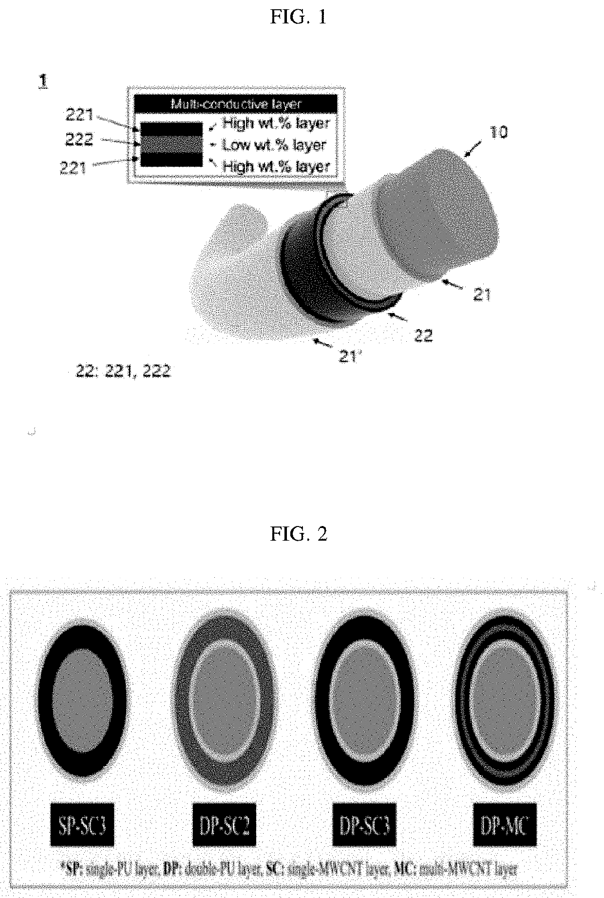
of Core-Shell Structured Fiber-Type Strain Sensor

Preparation of Fibrous Support Forming Core

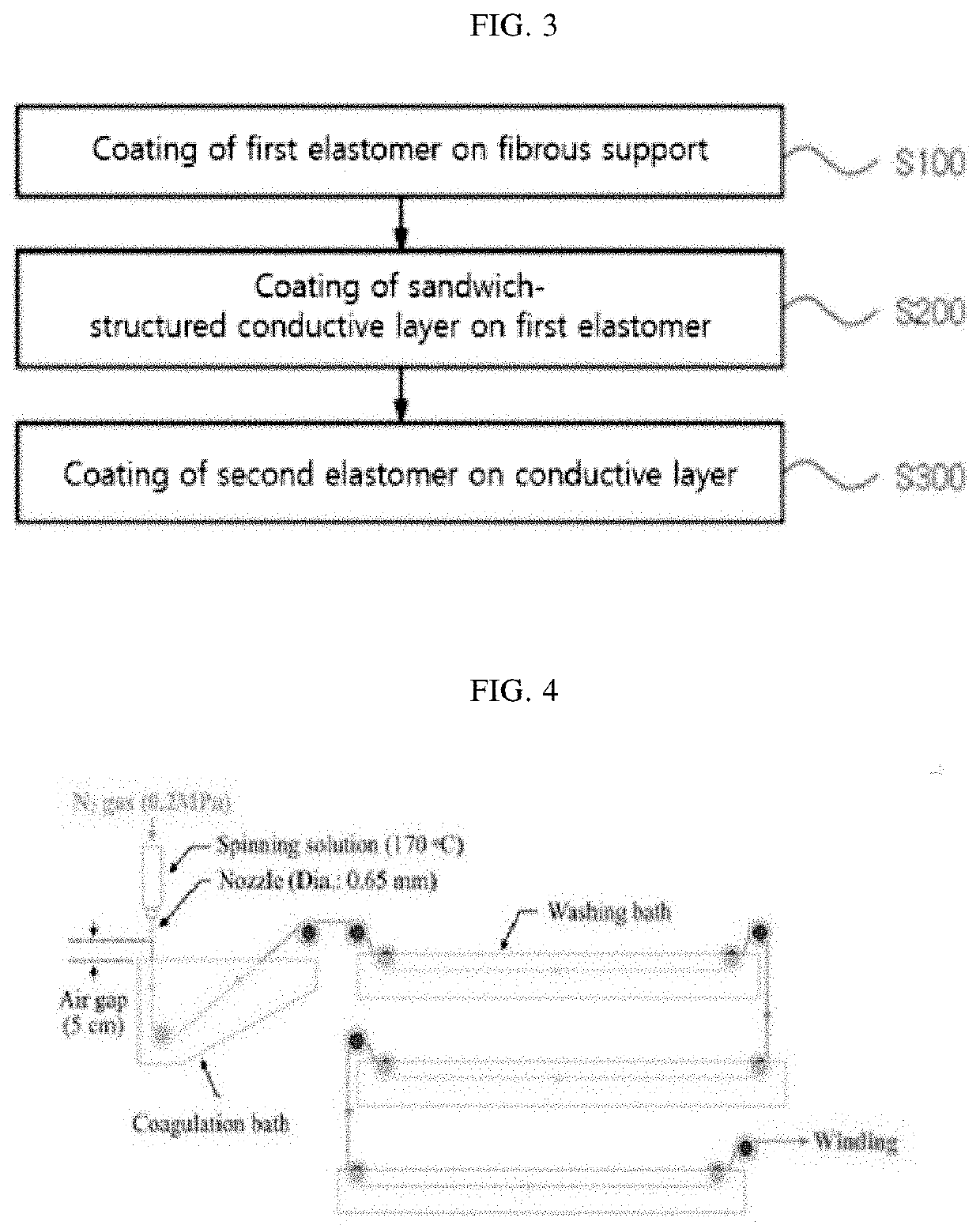
[0078]An ultrahigh-molecular-weight polyolefin-based fibrous support (core fiber) was prepared through a wet process. Specifically, the fibrous support was prepared using a dry-jet wet spinning system illustrated in FIG. 4.

[0079]First, UHMWPE powder (U050: average molecular weight 5×10⁶ g / mol, Korea Petrochemical) was mixed with paraffin oil (Sigma-Aldrich). Then, the mixture was kept at 100° C. for 24 hours for swelling in order to improve the chain mobility of UHMWPE. After preparing a 4 wt % solution by dissolving the swollen UHMWPE powder in paraffin oil at 170° C. for 4 hours, the molecular chain of the UHMWPE solution was stabilized by storing in a spinning solution syringe at the same temperature for 2 hours.

[0080]Then, UHMWPE core fiber was spun using the dry-jet wet spinning method. The UHMWPE fiber was prepared by supplying the UHMWPE solution to a nozzle under a N2 gas pressure of ...


PUM

PropertyMeasurementUnit
Electrical conductivityaaaaaaaaaa
Electrical resistanceaaaaaaaaaa
Ratioaaaaaaaaaa

Abstract

The core-shell structured fiber-type strain sensor of the present disclosure, which includes a fibrous support forming a core and a multilayered shell layer formed on the fibrous support, exhibits improved strength and stiffness due to the core fiber, exhibits improved noise level due to an elastomer layer and allows manufacturing of a fiber-type sensor with improved linearity of measurement signals due to a sandwich-structured conductive layer, is advantageous in that stable strain measurement is possible without acting as a defect in a composite structure.

Description

TECHNICAL FIELD[0001]The present disclosure relates to a core-shell structured fiber-type strain sensor and a method for manufacturing the same, more particularly to a core-shell structured fiber-type strain sensor with improved strength and stiffness due to a core fiber, improved noise level due to an elastomer layer, and improved linearity of measurement signals due to a sandwich-structured conductive layer, and a method for manufacturing the same.BACKGROUND ART[0002]Fiber-reinforced composite materials are used in various applications including aerospace and automobile industries due to excellent specific strength, specific stiffness, damping characteristics, etc. However, repeated application of load causes inter-laminar delamination that can lead to fracture at the interface between a reinforcing fiber and a matrix resin, which is the most vulnerable part of the composite. For this reason, researches are actively being carried out on structural health monitoring using a sensor ...

Claims


Application Information

Patent Timeline
IPC IPC(8): G01L1/22D06M15/564D06M11/74
CPCG01L1/2287G01L1/2206D06M2101/20D06M11/74D06M15/564H05K1/038G01M5/0041G01M5/0083G01B21/32B82B3/008D02G3/36
Inventor KIM, SEONG SUON, SEUNG YOON
Owner KOREA ADVANCED INST OF SCI & TECH
Why Eureka
Try Eureka