Hydrogen filling apparatus

a technology of filling apparatus and hydrogen, which is applied in the direction of electrochemical generators, container filling under pressure, and discharging methods of containers

Pending Publication Date: 2021-12-16
TOKYO TATSUNO CO LTD
View PDF0 Cites 4 Cited by
  • Summary
  • Abstract
  • Description
  • Claims
  • Application Information

AI Technical Summary

Benefits of technology

The present invention aims to provide a hydrogen filling apparatus for vehicles equipped with multiple large-capacity fuel tanks that can quickly fill with hydrogen gas while complying with a filling protocol. The invention is designed to save time compared to a case where each filling nozzle is attached to each fuel tank one by one. The invention includes a plurality of receptacles for hydrogen filling, each connected to a separate filling system, and a filling control device that can selectively use different modes to control the filling systems. The filling control device can quickly acquire data on the fuel tanks and perform hydrogen filling based on the data, regardless of whether the fuel tanks are independent of each other or communicate with each other in a vehicle. Overall, the invention allows for quick and efficient hydrogen filling of vehicles equipped with multiple fuel tanks.

Problems solved by technology

However, when supplying hydrogen to a large truck equipped with multiple large-capacity fuel tanks with a single filling nozzle, filling time may become very long depending on the diameter of a filling pipe in a hydrogen filling apparatus, the amount of hydrogen in a rear equipment, and the capacity of a compressor.

Method used


Image

  • Hydrogen filling apparatus
  • Hydrogen filling apparatus
  • Hydrogen filling apparatus

Examples


Embodiment Construction

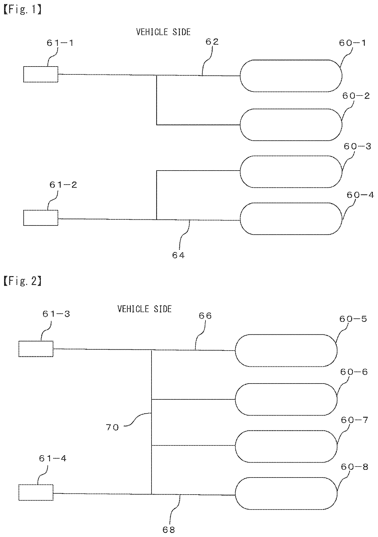
[0024]Hereinafter, an embodiment of the present invention will be described with reference to the accompanying drawings. In the below explanation, a vehicle (for example, a large truck or a bus) equipped with a plurality of large-capacity fuel tanks 60 will be exemplified with reference to FIGS. 1 and 2. The vehicle shown in FIG. 1 is a vehicle equipped with a plurality of fuel tanks 60 (four tanks in FIGS. 1 and 2), and is provided with a plurality of (two ports in FIGS. 1 and 2) hydrogen filling receptacles 61-1 and 61-2, a route 62 communicating the hydrogen filling receptacles 61-1 and the fuel tanks 60-1 and 60-2, a route 64 communicating the hydrogen filling receptacle 61-2 and the fuel tanks 60-3 and 60-4, and the route 62 and the route 64 are independent and do not communicate with each other. In other words, the fuel tanks 60-1 and 60-2 of the route 62 do not communicate with the fuel tanks 60-3 and 60-4 of the route 64 and are separated from each other.

[0025]When filling t...


PUM


Abstract

A hydrogen filling apparatus that can quickly fill vehicles equipped with multiple large-capacity fuel tanks with hydrogen gas while complying with filling protocol. The hydrogen filling apparatus (100) of the present invention includes: a plurality of filling systems; a filling control device (10, 20) for each of the filling systems; a filling pipe communicating with a rear facility in each of the filling systems; a set of filling members (for example, flow control valves, flow meters) interposed in each of the filling pipes and connected to each of the filling control devices; and a filling hose connected to each of the filling pipes, each filling hose having a filling nozzle at a tip; wherein one of the plurality of filling control devices has a function of selectively exerting a first control mode that controls only the filling system including the filling control device and a second control mode shared as a control device for the plurality of filling systems, and a switching means for switching between the first control mode and the second control mode in the one of the filling control devices is provided.

Description

CROSS-REFERENCE TO RELATED APPLICATIONS[0001]The present application claims priority to Japanese Patent Application No. 2020-100726 filed on Jun. 10, 2020 and Japanese Patent Application No. 2021-43099 filed on Mar. 17, 2021, the disclosures of which are incorporated herein by reference.STATEMENT RE: FEDERALLY SPONSORED RESEARCH / DEVELOPMENT[0002]Not ApplicableBACKGROUND1. Field of the Invention[0003]The present invention relates to a hydrogen filling apparatus for, for example, filling a fuel tank of a fuel cell vehicle with hydrogen gas as fuel.2. Description of the Related Art[0004]Vehicles that use hydrogen gas as fuel (fuel cell vehicles) have become widespread in connection with growing awareness of environmental issues in recent years. As such vehicles, not only passenger cars but also large trucks and buses used for logistics have been developed. The present applicant has proposed an apparatus for stably and efficiently filling such vehicles with hydrogen gas (see Japanese Pa...

Claims


Application Information

Patent Timeline
Patent Type & Authority Applications(United States)
IPC IPC(8): F17C5/06F17C13/02
CPCF17C5/06F17C13/025F17C2221/012F17C2270/0171F17C2250/03F17C2250/0626F17C2260/025F17C13/04F17C13/02F17C13/00F17C2270/0178F17C2250/0443F17C2223/0123F17C2223/036F17C2205/0326F17C2205/0329F17C2250/0636F17C2265/065F17C2270/0176F17C2270/0184F17C2270/0139Y02E60/32
Inventor YOSHIDA, YUICHI
Owner TOKYO TATSUNO CO LTD
Why Eureka
Try Eureka