Eureka AIR delivers breakthrough ideas for toughest innovation challenges, trusted by R&D personnel around the world.

Apparatus for generating real-time stereoscopic image and method thereof

a stereoscopic image and apparatus technology, applied in the field of video processing technology, can solve the problems of difficult image computation, high computational requirements, vacant pixels (holes), etc., and achieve the effect of rapid filling of holes in images and simplifying the complex methods of image inpainting

Active Publication Date: 2012-09-27
CHUNG HUA UNIVERSITY
View PDF7 Cites 30 Cited by
  • Summary
  • Abstract
  • Description
  • Claims
  • Application Information

AI Technical Summary

Benefits of technology

[0009]The purpose of the present invention is to simplify the complex methods of image inpainting and to design a method which is suitable for a hardware operation and can be applied to the hole filling technique required for generating the 3D stereoscopic image. Therefore, the present invention is hardware architecture which directly operates and generates real-time 3D stereoscopic images by rapidly filling the holes in the images.
[0019]Therefore, the present invention is able to timely generate the stereoscopic image, which is generated through hardware, so as to let the user more easily enjoy the produced stereoscopic vision, which meets the market demand for 3D displaying devices.

Problems solved by technology

After generating the stereoscopic image, the moved position of the object creates the problem of vacant pixels (holes), which need to be filled.
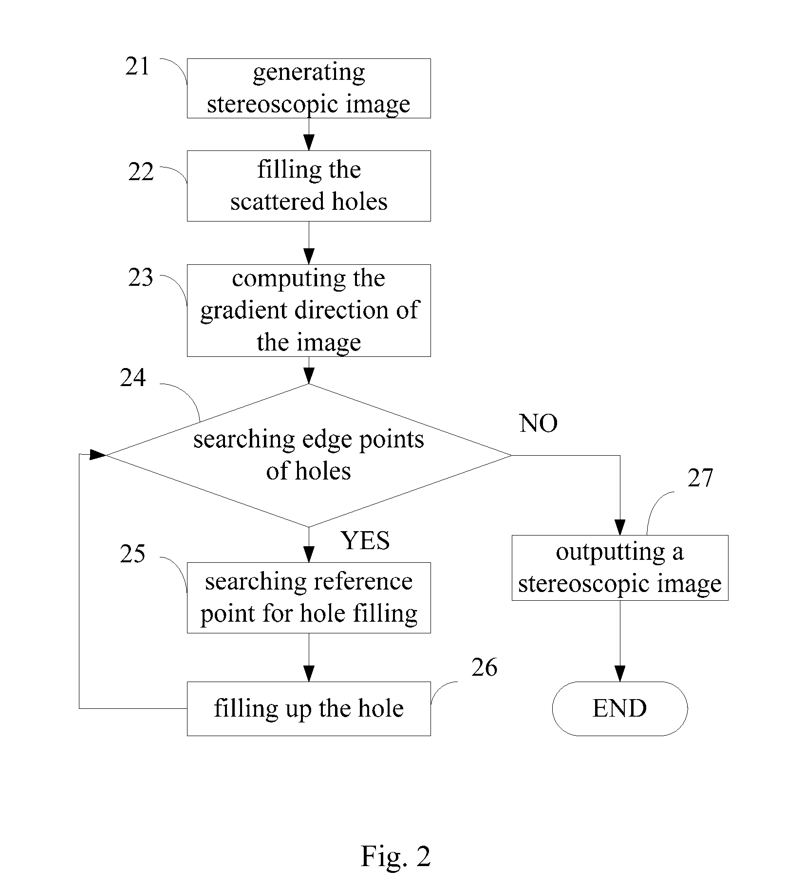
Most image inpainting methods progressively fill the holes, but the image orientation and similarity etc., make it hard to compute the image and are thus extremely time consuming; moreover to timely generate a 3D image, usually the hole is directly filled with the same pixel data as the neighboring pixel.
The image filling algorithm needs to continuously update the priority of the image filling, therefore the computational requirements are extremely high, and the computational method is constantly changing, and is unsuitable for hardware design, and the computational method therefore has to overcome these drawbacks through more fixed criteria.
There are more and more 3D stereoscopic products, but still no way of popularizing the technology for the average user; because it's difficult to realize a 3D stereoscopic image and the required filming devices are also extremely expensive, most television companies are unable to provide 3D stereoscopic programming, therefore most current use of this technology is restricted to gaming devices and the movie industry.
Current 3D stereoscopic image generating technologies rely on processing methods in software, and the current 3D stereoscopic images in the abovementioned gaming devices and movies therefore require computers, with no way to achieve the goal of real time operation and application.
The cost however is too high and therefore it's impractical and not beneficial.
Therefore, all kinds of methods are continuously being developed to increase the image processing speed, but processing still occupies a large part of the operation.
The time required for image inpainting however, is relatively short, as the image inpainting process simply fills the hole with the neighboring pixel information.
As the pixels are small, the effect of this image inpainting process is barely satisfactory, but if the pixels are bigger, the effects of the image inpainting process will not be ideal.
At the same time, the processing priority actions of the image inpainting algorithm are not easily designed on the hardware circuit, as it needs to keep updating the filling priority values, as every pixel needing to be filled has to be continuously updated, which is extremely time consuming.

Method used


Image

  • Apparatus for generating real-time stereoscopic image and method thereof
  • Apparatus for generating real-time stereoscopic image and method thereof
  • Apparatus for generating real-time stereoscopic image and method thereof

Examples


Embodiment Construction

[0038]While the present invention has been described in connection with what are considered the most practical and preferred embodiments, it is understood that this invention is not limited to the disclosed embodiments but is intended to cover various arrangements included within the spirit and scope of the broadest interpretations and equivalent arrangements.

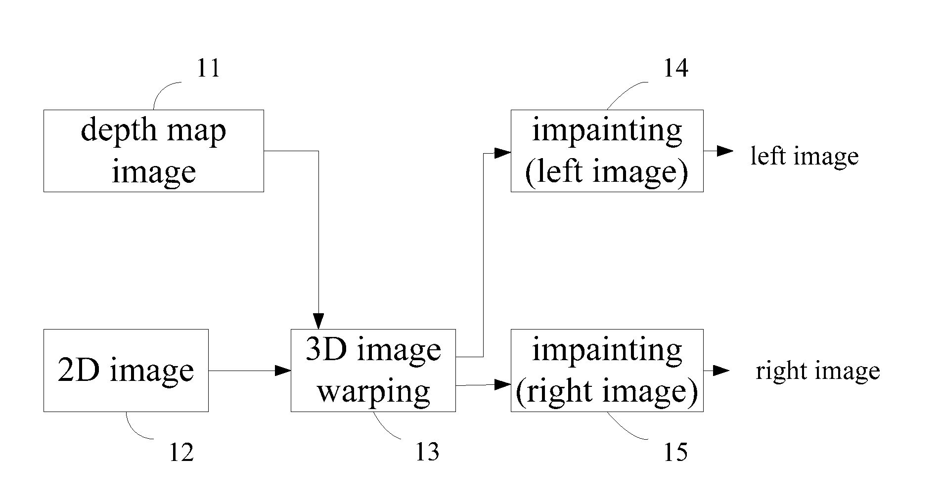
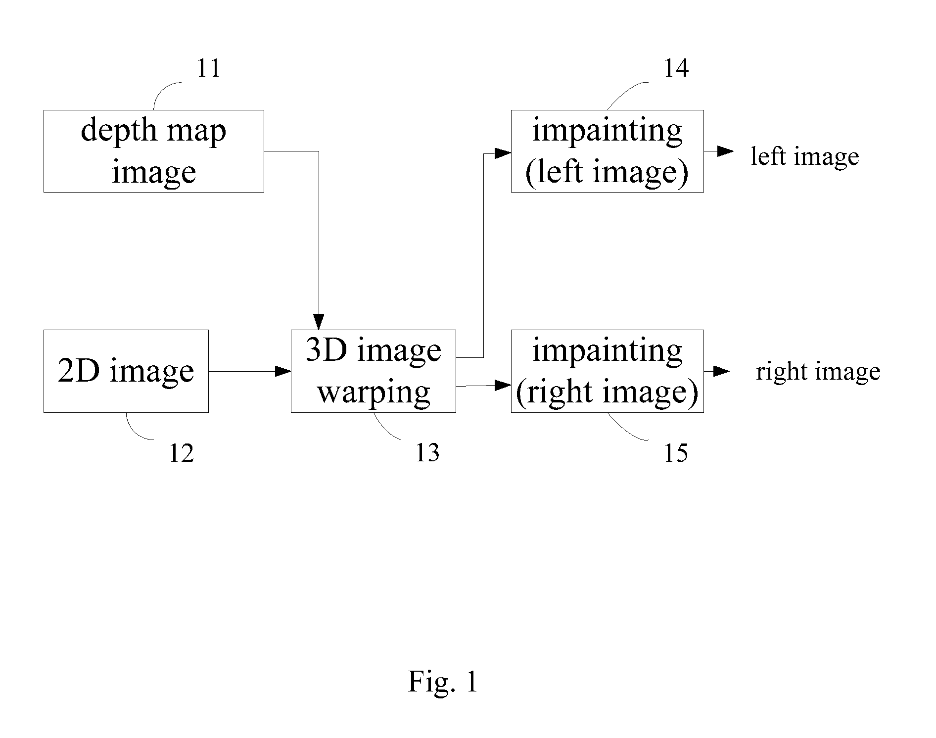
[0039]Please refer to FIG. 1, which is a schematic diagram showing the system configuration of the present invention. In order to directly transform the original 2D images 12 into 3D stereoscopic images, the depth camera must be used to obtain depth information, or the stereo camera is used to compute the relative depth information, or estimating the relative depth information of the image by analyzing the image feature, which utilizes color, clarity, geometric position and object size etc. In this embodiment, the depth map image 11 is obtained by utilizing the method of analyzing the image feature, then the 2D images 12 and th...


PUM


Abstract

Disclosed is an apparatus and method for generating a real-time stereoscopic image from depth map. According to the depth information of the image, a depth-image-based rendering (DIBR) algorithm is used to shift (or move) the position of the object in the image to generate the stereoscopic image with parallax. When the object is shifted (or moved) away from its original position, a hole will occur in the original position. Therefore an image inpainting algorithm is developed to fill the hole. In order to achieve the real-time application, a hardware architecture and method have been developed to accomplish the DIBR and image inpainting algorithm.

Description

BACKGROUND OF THE INVENTION[0001]1. Field of the Invention[0002]The present invention relates to a video processing technology, in particular, to a apparatus for transforming 2D images and videos into 3D images and videos and the method thereof[0003]2. Description of Related Art[0004]The commonly used 3D image generating technology, like DIBR (Depth Image Based Rendering), utilizes the image depth information and the geometric relations of a stereo camera (Toe-in or Off-axis are utilized in the camera setup), to change the position of the object in the image, thus generating a group of virtual stereoscopic images with parallax.[0005]After generating the stereoscopic image, the moved position of the object creates the problem of vacant pixels (holes), which need to be filled. Most image inpainting methods progressively fill the holes, but the image orientation and similarity etc., make it hard to compute the image and are thus extremely time consuming; moreover to timely generate a 3...

Claims


Application Information

Patent Timeline
Patent Type & Authority Applications(United States)
IPC IPC(8): H04N13/00
CPCH04N13/0011H04N13/0271H04N13/0037H04N13/111H04N13/15H04N13/271
Inventor CHENG, FANG-HSUANCHANG, YU-WEI
Owner CHUNG HUA UNIVERSITY
Why Eureka
Eureka Blog
Learn More