
Micro-led display and manufacturing method therefor

a technology of light-emitting diodes and led displays, which is applied in the direction of semiconductor/solid-state device manufacturing, electrical apparatus, and semiconductor devices. it can solve the problems of low production yield, high price, and inappropriate application of near-field displays, so as to improve the degree of integration, improve the mass-production yield, and improve the yield

Active Publication Date: 2021-12-02
SAMSUNG ELECTRONICS CO LTD
View PDF4 Cites 5 Cited by
  • Summary
  • Abstract
  • Description
  • Claims
  • Application Information

AI Technical Summary

Benefits of technology

The patent text describes various methods for manufacturing a micro LED display panel with improved integration and yield. It also includes methods for testing and correcting errors in the micro LED array package, as well as techniques for easily mounting and reworking components on a substrate. The technical effects of the patent text include increased integration and yield of micro LED display panels, improved testing and correction of errors, and improved efficiency in mounting and reworking components.

Problems solved by technology

Although an Organic Light Emitting Diode (OLED) panel is drawing attention as a new display for replacing a Liquid Crystal Display (LCD) panel, a high price issue caused by a low production yield, large size and reliability issues, or the like still remains as problems to be solved.
However, in order to implement the display, a micro LED (μLED) corresponding to a current pixel needs to be developed first, and there are issues to be solved, such as how to pick up micro LEDs of dozens of micrometers (μm) and how precisely the micro LEDs will be placed on a Printed Circuit Board (PCB), and how to arrange input / output terminals to be electrically coupled with a main PCB.
In case of a display which uses an LED package, since the LED package having a size of several millimeters (mm) is basically used, it is inappropriate to be applied to a near-field display.

Method used


Image

  • Micro-led display and manufacturing method therefor
  • Micro-led display and manufacturing method therefor
  • Micro-led display and manufacturing method therefor

Examples


Embodiment Construction

[0027]Hereinafter, various embodiments of the disclosure are described with reference to the accompanying drawings. However, it should be appreciated that this is not intended to limit the technological features set forth herein to particular embodiments and include various changes, equivalents, or replacements for an embodiment of the disclosure. With regard to the description of the drawings, similar reference numerals may be used to refer to similar or related elements.

[0028]An expression “have”, “may have”, “include” or “may include” or the like used in the disclosure is intended to indicate a presence of a corresponding characteristic (e.g., a number, a function, an operation, or a component such as a component), and should be understood that there are additional possibilities of one or more other characteristics.

[0029]In the disclosure, an expression “A or B”, “A and / or B”, or “one or more of A and / or B” or the like may include all possible combinations of items enumerated tog...


PUM

PropertyMeasurementUnit
sizeaaaaaaaaaa
sizeaaaaaaaaaa
photosensitiveaaaaaaaaaa

Abstract

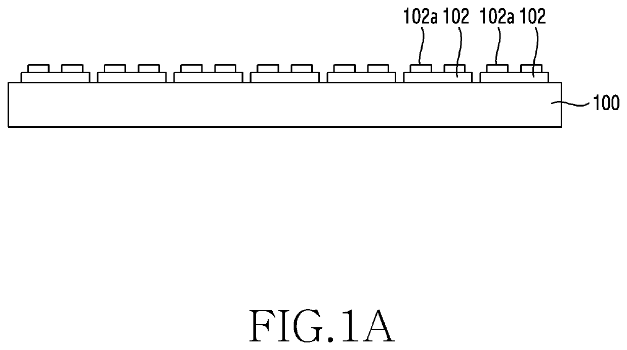
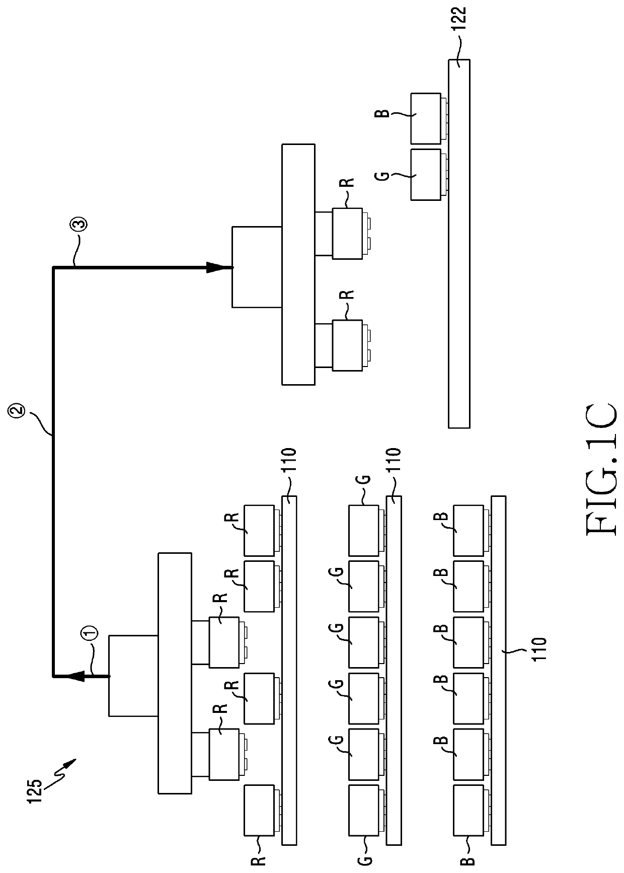
The disclosure describes a micro Light Emitting Diode (LED) display. The display may include a Printed Circuit Board (PCB) including a plurality of solder pads, a micro LED package including a plurality of micro LED chips, and a plurality of solder electrodes which bond the micro LED chips onto the solder pads of the PCB. The micro LED package may be re-arranged in an Red Green Blue (RGB) state on a temporary fixing film by using a pickup device in accordance with a display pixel configuration, after the micro LED chips are attached to a carrier film.

Description

TECHNICAL FIELD[0001]Various embodiments of the disclosure relate to a micro light emitting diode (LED) display and a manufacturing method thereof.BACKGROUND ART[0002]Although an Organic Light Emitting Diode (OLED) panel is drawing attention as a new display for replacing a Liquid Crystal Display (LCD) panel, a high price issue caused by a low production yield, large size and reliability issues, or the like still remains as problems to be solved. Researches on a technique for producing a display panel by directly mounting an LED which emits Red (R), Green (G), and Blue (B) on a substrate have been attempted as a new product to compensate for this problems.[0003]However, in order to implement the display, a micro LED (μLED) corresponding to a current pixel needs to be developed first, and there are issues to be solved, such as how to pick up micro LEDs of dozens of micrometers (μm) and how precisely the micro LEDs will be placed on a Printed Circuit Board (PCB), and how to arrange in...

Claims


Application Information

Patent Timeline
Patent Type & Authority Applications(United States)
IPC IPC(8): H01L25/075H01L33/62H01L33/00H01L25/16
CPCH01L25/0753H01L33/62H01L33/52H01L25/167H01L33/0095H01L33/48H01L27/156H01L21/67712H01L21/67721H01L21/027H01L33/02H01L33/0093H01L2933/005H01L2933/0066
Inventor LEE, YOUNGCHULPARK, TAESANGLEE, KYOREELEE, TACKMOHEO, GYUNMOON, YOUNGJUNCHOI, WON
Owner SAMSUNG ELECTRONICS CO LTD
Learn More