Asynchronous temperature control integrated device

a temperature control and integrated device technology, applied in the direction of instruments, liquid/fluent solid measurement, signalling system, etc., can solve the problems of increasing power consumption, increasing the accumulation of power consumption, and consuming a large amount of electrical power, so as to improve the overall airflow, improve the temperature control conditions, and reduce the internal temperature of the system

Pending Publication Date: 2021-12-02
EVGA CORPORATION
View PDF3 Cites 2 Cited by
  • Summary
  • Abstract
  • Description
  • Claims
  • Application Information

AI Technical Summary

Benefits of technology

[0009]The primary objective of the present invention is to conduct temperature monitoring for heat sources located at different sites on a graphics card and to individually control heat dissipation devices at locations corresponding to different ones of the heat sources such that amounts of output power of the heat dissipation devices are generally proportional to the temperatures of the heat sources, and to even further drive, in a collaborative manner, an external fan to enhance overall airflow, reduce system internal temperature, and achieve bettered conditions of temperature control.
[0011]A user, when operating the present invention, may find that two major heat sources of the graphics card body (which are respectively the graphics processor and the power supply circuit) are each provided with a heat dissipation device and the temperatures of the two heat sources are respectively detected by the first temperature sensor and the second temperature sensors so that the control device may regulate the output power of the first heat dissipation device or the second heat dissipation devices individually, based on the results of detection to correspondingly handle different levels of heat generation. As such, excessive consumption of electrical power can be avoided and the amounts of output power of the heat dissipation devices can be adjusted in a timely and individual manner. Further, the graphics card body is connected, via the external fan connection port, with an external fan arranged on a computer enclosure or case to thereby enhance overall airflow, reduce system internal temperature, and achieve bettered conditions of temperature control.
[0012]Thus, the present invention may overcome the drawbacks of the known fan speed control systems that suffer shortcoming by synchronously adjusting the rotational speeds of the fans that may not timely responsive to desired heat dissipation performance and may consume extra electrical power.

Problems solved by technology

Considering a heat dissipation fan, a high-speed operation indicates a high efficiency of heat dissipation and would also amount to increasing accumulation of power consumption.
If heat is not properly and timely removed, then the hardware might get down due to heat, and on the other hand, continuously keeping heat speed operation would consume a large amount of electrical power and may burden the power supply device.
(1) There may be differences of temperature among all the heat sources and control of adjusting rotational speeds in a synchronous manner may suffer difficulty for decision making. If a low-temperature heat source is taken as a reference for adjustment, then the heat generated by a high-temperature heat source may not be effectively removed. On the other hand, if the high-temperature heat source is taken as a reference, then extra electrical power may get wasted at the low-temperature heat source.
(2) The rotational speeds of the fans are adjusted in a passive manner according to the measurements of temperatures. Thus, when a heat source is put into high power operation and thus generates a huge amount of heat, adjusting the rotational speeds in such a way may not be timely responsive and the heat source may reach a temperature beyond a tolerable upper temperature limit.
(3) The fan on the graphics card is independent of an external fan and the rotational speeds thereof can only be controlled separately, making it impossible to control and manage an overall airflow inside a computer enclosure or case.

Method used


Image

  • Asynchronous temperature control integrated device
  • Asynchronous temperature control integrated device
  • Asynchronous temperature control integrated device

Examples


Embodiment Construction

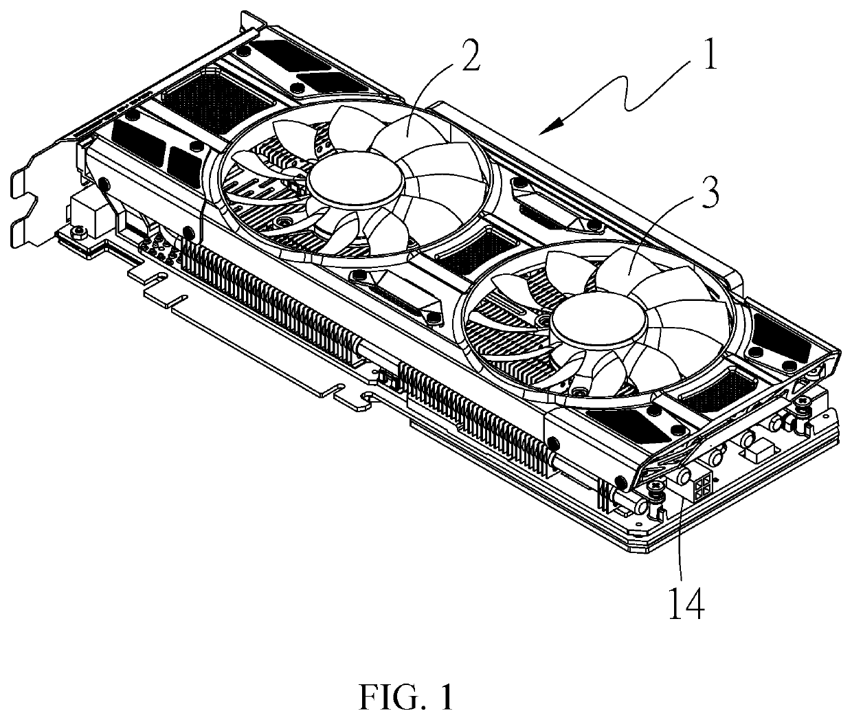
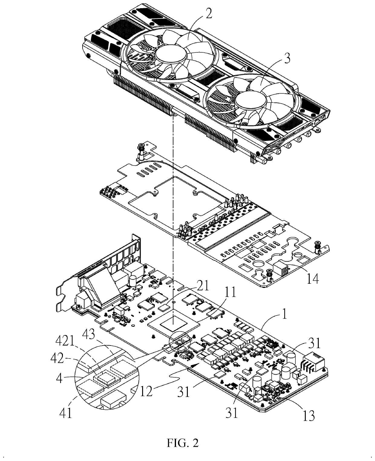
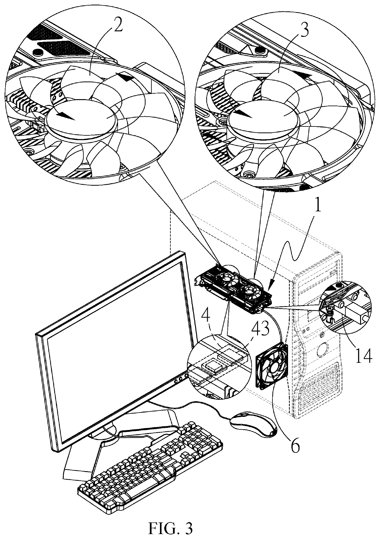
[0023]Referring to FIGS. 1 and 2, it can be clearly seen that the present invention comprises:

[0024]a graphics card body 1, the graphic card body 1 comprising a graphics processor 11 and a power supply circuit 12 arranged at one side of the graphics processor 11;

[0025]at least one external fan connection port 14, which is arranged on the graphics card body 1;

[0026]a first heat dissipation device 2, which is arranged on the graphics processor 11, a heat dissipation fan being taken as an example in the present invention;

[0027]at least one first temperature sensor 21, which is arranged at one side of the first heat dissipation device 2;

[0028]a second heat dissipation device 3, which is arranged on the power supply circuit 12, a heat dissipation fan being taken as an example in this invention;

[0029]a plurality of second temperature sensors 31, which are arranged at one side of the second heat dissipation device 3;

[0030]a plurality of light emission elements 13, which are arranged on the...


PUM


Abstract

An asynchronous temperature control integrated device includes a graphics card body including a graphics processor and a power supply circuit, at least one external fan connection port, a first heat dissipation device, at least one first temperature sensor, a second heat dissipation device, a plurality of second temperature sensors, a plurality of light emission elements, and a control device including an externality control member, a high-power drive module, and a scenario database. Thus, two groups of heat dissipation device and temperature sensor are provided to respectively detect the temperatures of two major heat sources on the graphics card body, and the heat dissipation performances of the two heat dissipation devices are individually controllable to make timely and efficient operations of the heat dissipation devices, and also to collaboratively drive an external fan to thereby enhance overall airflow, reduce system internal temperature, and achieve bettered conditions of temperature control.

Description

CROSS-REFERENCE TO RELATED APPLICATIONS[0001]This is a continuation-in-part of co-pending U.S. patent application Ser. No. 15 / 436,736 filed on Feb. 17, 2017.TECHNICAL FIELD OF THE INVENTION[0002]The present invention relates generally to an asynchronous temperature control integrated device, and more particularly to an asynchronous temperature control integrated device that conducts an instantaneous and effective driving operation, in a manner of being free of extra power consumption, on individual heat sources located on a graphics card to individually control heat dissipation devices associated with the heat sources and is also operable to drive an external fan in a collaborative manner.DESCRIPTION OF THE PRIOR ART[0003]The advent of the high image quality era causes display screens, such as televisions, computers, game consoles, and movies evolving step by step from DVD, blue ray, to 4K, among which a major difference is “definition” or “resolution”. For computers, a high-resolut...

Claims


Application Information

Patent Timeline
Patent Type & Authority Applications(United States)
IPC IPC(8): G06F1/20H05K7/20G06F1/26G08B21/18G08B5/36
CPCG06F1/206H05K7/20209G08B5/36G08B21/18G06F1/26G06F1/20
Inventor HAN, TAI-SHENG
Owner EVGA CORPORATION
Why Eureka
Try Eureka