
Heat pump having improved efficiency

Pending Publication Date: 2021-12-02
LEE DONG WON
View PDF6 Cites 2 Cited by
  • Summary
  • Abstract
  • Description
  • Claims
  • Application Information

AI Technical Summary

Benefits of technology

The heat pump control method described in this patent improves efficiency by allowing the heat pump to set targets for high and low pressures under different load conditions. This results in better performance and reduces the use of electricity by the compressor.

Problems solved by technology

In general, it is known that an air conditioner consumes about 20 times more electricity than an electric fan.
If a difference between an inlet pressure and an outlet pressure of the compressor increases, the compressor consumes more electricity even operating at the same frequency.
However, a conventional a conventional heat pump has a problem of low efficiency because it is not controlled by setting the inlet pressure and the outlet pressure of the compressor as the first-priority achievement goal.
In US 2009 / 00137001 and application number KR 10-2016-0072934, the target pressure (low pressure) is achieved with the compressor having large power consumption, so that there is a problem of great fluctuation in power consumption.

Method used


Image

  • Heat pump having improved efficiency
  • Heat pump having improved efficiency
  • Heat pump having improved efficiency

Examples


first embodiment

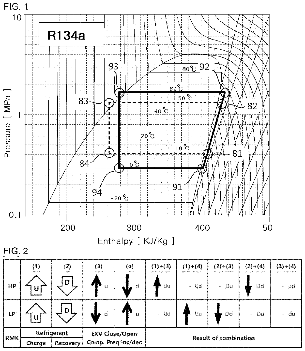
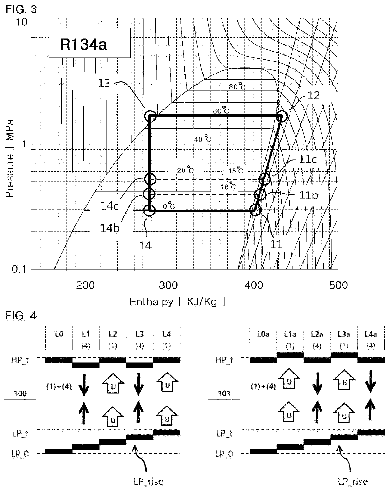
[0050]Now, an embodiment (air conditioner cooling mode) of controlling the evaporation temperature to be higher in the heat pump according to the present invention will be described with reference to FIGS. 2 to 4.

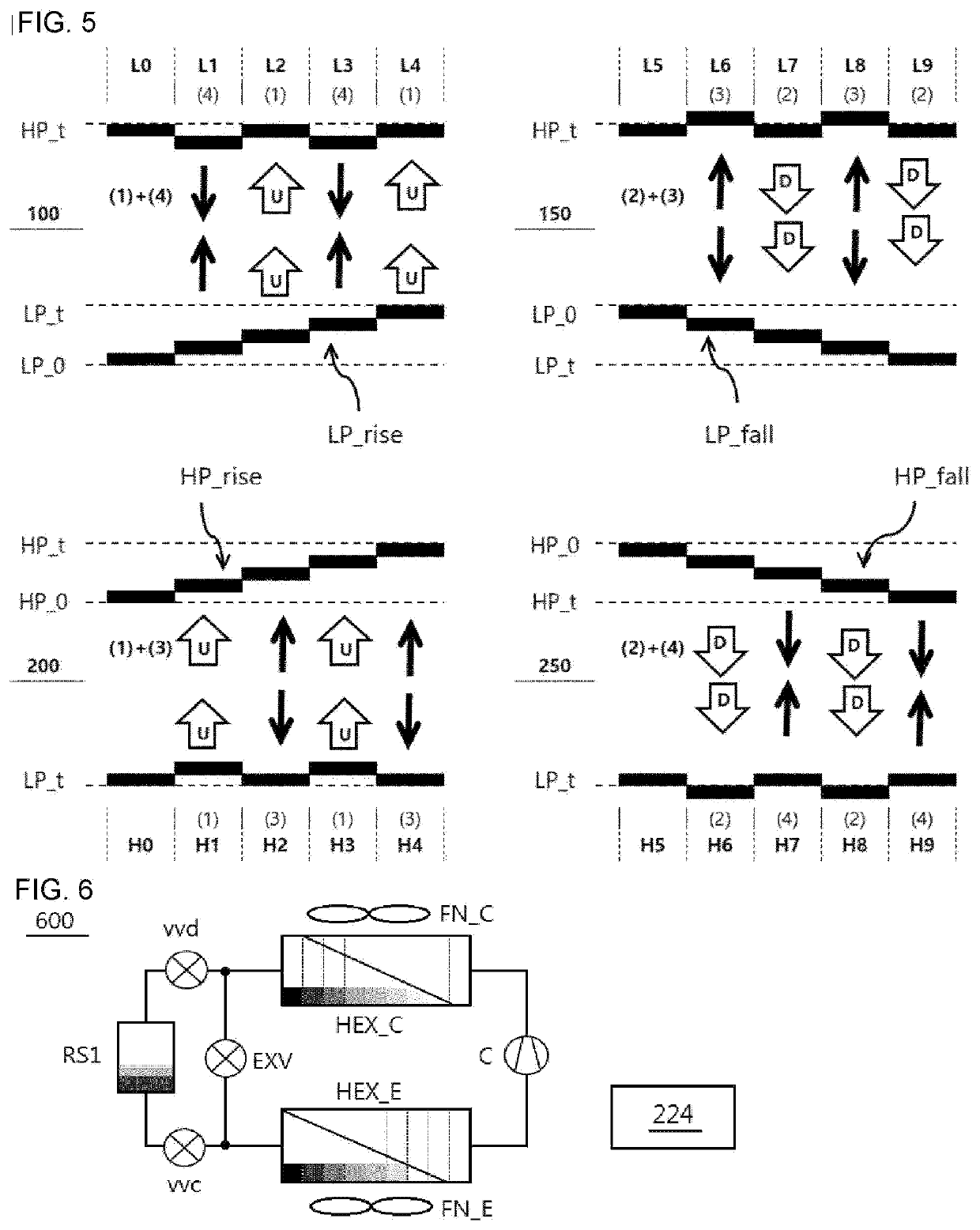
[0051]FIG. 4 shows examples of a procedure for controlling the evaporation temperature of the evaporator to be higher. A control procedure 100 is a case of sequentially performing the fourth control (4) and the first control (1) twice. In the initial state L0, the controller sets the target low pressure (LP_t) higher than the current low pressure (LP_0) according to certain necessity. Then, the low pressure is different from the target value, and the controller performs the fourth control (4) so as to make the low pressure equal to the target value. As a result, the low pressure rises, and the high pressure falls, so that a state L1 is obtained. The evaporation temperature becomes higher because the low pressure rises as desired, but the condensation temperature becomes low...

second embodiment

[0072]Now, an example of a heat pump 600 adapted for the present invention will be described with reference to FIG. 6.

[0073]The heat pump 600 is configured by connecting a “circuit” including a compressor (C), a condenser (HEX_C), an expansion valve (EXV), and an evaporator (HEX_E) through a closed refrigerant line. In addition, a refrigerant storage tank (RS1) is installed in parallel with the expansion valve (EXV). Between the inlet of the expansion valve (EXV) and the inlet of the tank (RS1), a recovery valve (vvd) for recovering the refrigerant from the “circuit” is installed. Also, between the outlet of the expansion valve (EXV) and the outlet of the tank (RS1), a charging valve (vvc) for charging the refrigerant to the “circuit” is installed. Hereinafter, the refrigerant storage tank (RS1), the recovery valve (vvd), and the charging valve (vvc) will be collectively referred to as “refrigerant (charging) amount adjusting means (RAAM)”.

[0074]Hereinafter, an example of charging t...

third embodiment

[0081]Now, an example of a method for controlling a cooling mode in the heat pump 600 adapted for the present invention will be described with reference to FIG. 6. The circuit configuration of the heat pump 600 has been described above and thus will be omitted. In the present invention, a controller 224 preferably includes the following first to seventh roles.

[0082]1) Variable Capacity Compressor Control: The controller 224 controls the compressor (C) to compress the set amount of refrigerant per unit time (g / s). The compression amount (g / s) can be calculated by referring to the cooling load. In case of the inverter compressor (C), it operates at a frequency set in response to the load. If the low pressure and super-heating degree (SC) are kept constant, the density of the refrigerant is constant under that condition, and thus the amount of refrigerant per unit time (g / s) compressed by the compressor (C) will be calculated for each driving frequency (hereinafter, “refrigerant compre...


PUM


Abstract

A heat pump configured by connecting a circuit including a variable capacity compressor, a condenser, an expansion valve, and an evaporator through a closed refrigerant line, includes a condenser fan, an evaporator fan, a refrigerant amount adjusting means for charging or recovering a refrigerant in or from the circuit, and a controller. Roles of the controller include setting a target pressure inside an outdoor heat exchanger y referring to an outside temperature and a load, setting a target pressure inside an indoor heat exchanger by referring to an inside temperature and a set temperature, setting a target sub-cooling degree and a target super-heating degree, and controlling both of the fans to either adjust temperature or adjust pressure.

Description

BACKGROUND[0001]The present invention relates to a heat pump having improved efficiency.[0002]A heat pump is a device that transfers heat from a heat source to a destination called “heater sink”. The heat pump absorbs heat from a cold space and dissipates heat into a warm space. Representative examples of the heat pump are a refrigerator and an HVAC (Heating Ventilating and Air Conditioning) device such as an air conditioner. In addition, devices using the heat pump are a water purifier providing cold / hot water, a dryer, a washing machine, a vending machine, and the like.[0003]The heat pump is composed of a compressor, a condenser, an expansion valve, and an evaporator. In general, it is known that an air conditioner consumes about 20 times more electricity than an electric fan. Based on this calculation, the compressor consumes 90% electricity, and each of a condenser fan and an evaporator fan consume 5% electricity.[0004]In order to reduce the power consumption of the compressor, ...

Claims


Application Information

Patent Timeline
IPC IPC(8): F25B49/02F25B30/02F25B43/00
CPCF25B49/025F25B30/02F25B2600/112F25B2500/19F25B2600/111F25B43/006B60H1/00F25B45/00F25B49/02F25B2600/0253F25B2700/2106F25B2700/2116F25B2700/2117F25B2600/2513F25B2345/003F25B41/20Y02B30/70F25B2600/021F25B43/043
Inventor LEE, DONG WON
Owner LEE DONG WON
Learn More