
Method for Detecting Coking in the Inlet Section of an Internal Combustion Engine With a Variable Inlet Valve Lift Controller

Active Publication Date: 2021-12-02
BAYERISCHE MOTOREN WERKE AG
View PDF0 Cites 0 Cited by
  • Summary
  • Abstract
  • Description
  • Claims
  • Application Information

AI Technical Summary

Benefits of technology

[0020]The method according to the invention makes it possible to objectively identify coking in the inlet section of an internal combustion engine with direct fuel injection. The objective identification is performed by measurement and the use of further parameters which are available in the vehicle rather than by subjective visual assessment. Cleaning and/or repair is thus performed only when this is actually objectively required.
[0021]With the use of the method described herein, dismantling of the internal combustion engine solely for the visual assessment of coking is not necessary. Coking can be identified in a very short time. The duration for identifying w

Problems solved by technology

Here, the coking tendency tends to increase with the use of fuels and oils of low quality and in the case of low-load driving profiles.
The coking results in an impairment of the running smoothness during cold idling and can lead to increased fuel consumption and complaints with regard to warm-up driving characteristics.
A coking film for example at the top on the valve neck between valve disk and valve shank can disrupt the tumbling flow, such that the idling rotational speed fluctuates to a greater degree and, in the extreme case, misfiring may even occur.
A coking film may even lead, as a flow resistance, to a drop in power owing to inadequate cylinder charging.
Furthermore, a coking film on the inlet valve or on the valve opening can prevent a correct closure of the valve, such that compression losses and sporadic misfiring occur.
The v

Method used


Image

  • Method for Detecting Coking in the Inlet Section of an Internal Combustion Engine With a Variable Inlet Valve Lift Controller

Examples


Example

DETAILED DESCRIPTION OF THE DRAWING

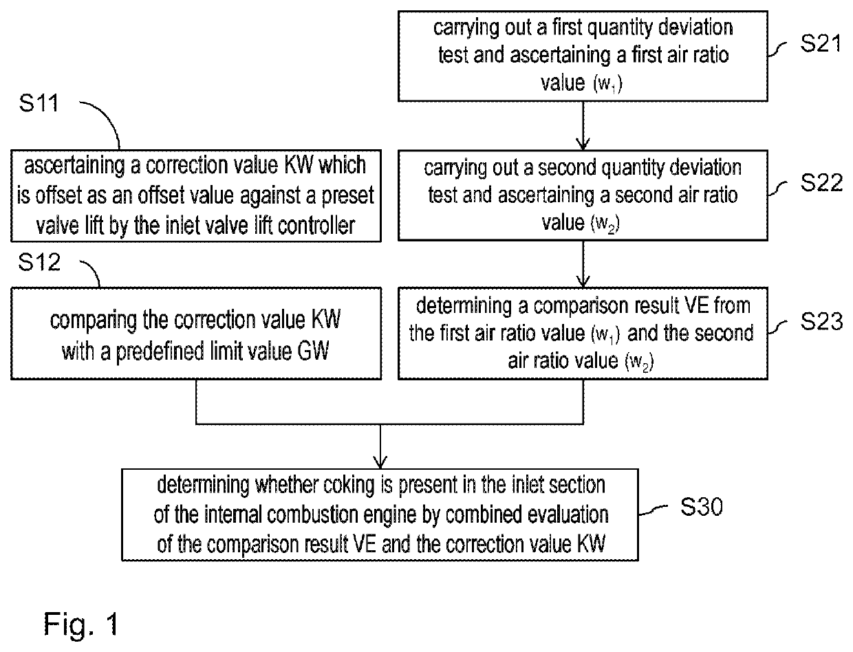
[0037]FIG. 1 shows an exemplary flow diagram of the method for detecting coking in the inlet section of an internal combustion engine. The internal combustion engine has one or more cylinder banks, wherein a respective cylinder bank comprises multiple cylinders with in each case one combustion chamber formed therein and at least one injection nozzle. In particular, exactly one injection nozzle is provided in each combustion chamber. A common air mass flow is fed to the combustion chambers of a respective cylinder bank. Likewise, a common exhaust-gas flow is discharged from the combustion chambers of a respective cylinder bank. The internal combustion engine has direct fuel injection, and is in particular an Otto-cycle engine with gasoline direct injection and fully variable valve controller. The control of the internal combustion engine is performed by means of various control parameters stored in an engine controller.

[0038]The internal combustion ...


PUM


Abstract

A method detects coking in the inlet section of an internal combustion engine with direct fuel injection, a throttle valve and a variable inlet valve lift controller. A correction value calculated by the inlet valve lift controller as an offset value with a preset valve lift is determined. In parallel, a first quantity deviation test is carried out by which a first air ratio value is determined, which is formed from a first lambda value measured during the first quantity deviation test and a desired lambda value of the fuel combustion in the combustion chambers of the internal combustion engine, wherein, in the first quantity deviation test a load control process is carried out by way of the variable inlet valve lift controller. In a second quantity deviation test, a second air ratio value is determined which is formed from a lambda value measured during the second quantity deviation test and a desired lambda value of the fuel combustion. In the second quantity deviation test a load control process is carried out by way of the throttle valve. A comparison value is formed from the first air ratio value and the second air ratio value. Whether coking is present in the inlet section of the internal combustion engine is determined by combined evaluation of the comparison result and of the correction value.

Description

BACKGROUND AND SUMMARY OF THE INVENTION[0001]The invention relates to a method for detecting coking in the inlet section of an internal combustion engine which has direct fuel injection, a throttle flap and a variable inlet valve lift controller, and to a corresponding engine test unit.[0002]In the case of Otto-cycle engines with gasoline direct injection, coking of the inlet section can occur, in particular at the inlet valve (for example at the valve neck) or in the inlet channel at the valve opening. In the case of such coking, carbon-like material accumulates in the inlet section. A cause for the coking tendency in Otto-cycle engines with gasoline direct injection is that, in the case of Otto-cycle engines with gasoline direct injection, no continuous cleaning purging of the inlet section, for example of the inlet valve, with gasoline occurs, because the fuel is injected directly in the combustion chamber. Oil residues from the crankcase ventilation system, the valve shank seal ...

Claims


Application Information

Patent Timeline
IPC IPC(8): F02D13/02F02D41/00F02D41/14F02D41/22F02D41/24
CPCF02D13/0226F02D41/0002F02D41/1456F02D2041/001F02D41/2451F02D2041/002F02D41/22Y02T10/12Y02T10/40
Inventor KOEHLER, JOERG
Owner BAYERISCHE MOTOREN WERKE AG
Learn More