Centrifuge having a drum tool

a technology of centrifuge and drum, which is applied in the direction of centrifuges, etc., can solve the problems of increasing the burriness the risk of local plastic deformation of the torque transmission surface on the drum locking ring, and the progressive wear of the torque transmission surface, so as to simplify the opening and closing process of the drum

Pending Publication Date: 2021-11-25
GEA MECHANICAL EQUIP
View PDF2 Cites 0 Cited by
  • Summary
  • Abstract
  • Description
  • Claims
  • Application Information

AI Technical Summary

Benefits of technology

The invention prevents the parts of a screwed-together drum from getting stuck and reduces the negative effects of using a wrench designed to control the opening process. This results in a simpler and more efficient process.

Problems solved by technology

Due to the required play of the ring spanner to the torque transmission surfaces on the drum locking ring, there is a risk of local plastic deformation of the torque transmission surfaces on the drum locking ring due to impulse loading resulting from the abrupt application of force to the ring spanner.
Depending on the frequency of loosening and retightening, there is progressive wear on the torque transmission surfaces, which can be accompanied by increasing burriness of the torque transmission surfaces, which must be minimized.
However, according to the technical teaching of both publications, lever forces are used that act on one side of the screw connection of the drum locking ring, which can still lead to tilting of the threads and thus to seizing of the screw connection.
A further disadvantage of the proposed solution from DE 2615 058 and DE 484 735 is that the drum must be fixed mechanically, as the lever mechanism requires a counter-torque to the torque of the lever.

Method used


Image

  • Centrifuge having a drum tool
  • Centrifuge having a drum tool
  • Centrifuge having a drum tool

Examples


Embodiment Construction

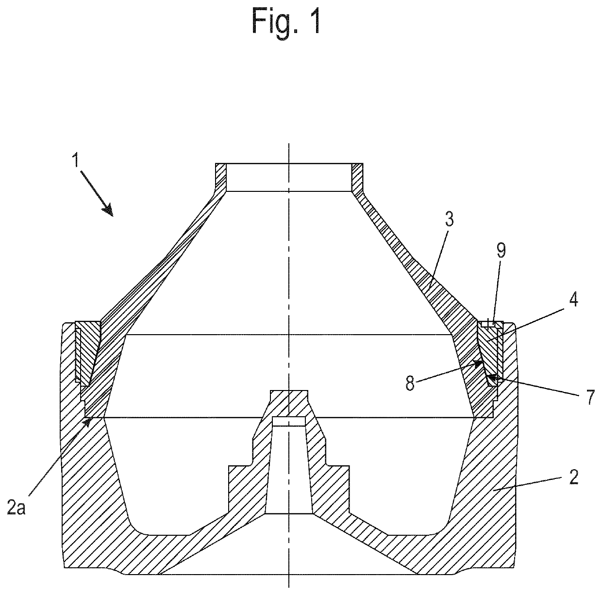
[0029]FIG. 1 shows a drum 1 of a centrifuge—here an example of a separator with vertical axis of rotation.

[0030]Drum 1 has several drum parts. These include a lower drum part 2 and an upper drum part 3 as well as a drum locking ring 4. A screw connection is formed between at least two of these parts. This must be tightened and loosened with a tool in order to open or close the drum.

[0031]Here the upper drum part 3 is inserted into the lower drum part 2. There it rests on an inner radial collar 2a of the lower drum part 2.

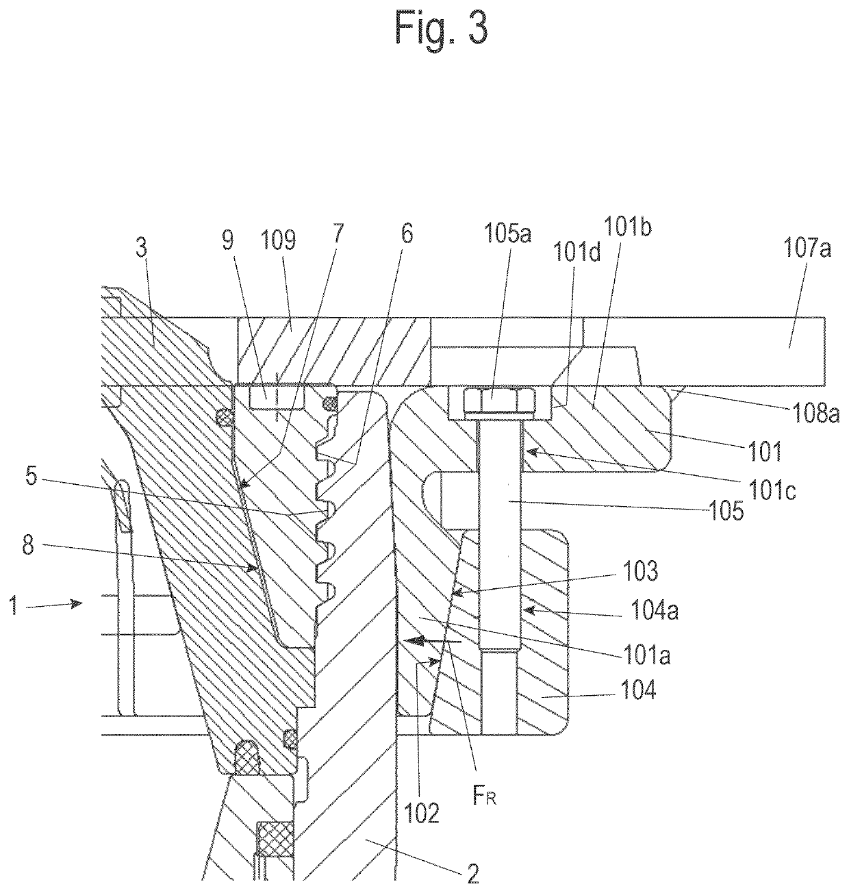
[0032]A gap is formed between the outer circumference of the conically formed upper drum part 3 and the inner circumference of the lower drum part 2, which in any case is cylindrical in sections. The locking ring 4, which is also cylindrical radially on the outside, is inserted into this gap. The locking ring 4 has an external thread and the lower drum part 2 a corresponding internal thread (see also FIG. 3). The locking ring 4 is screwed into the lower drum part 2....


PUM


Abstract

A separator for centrifugally processing includes a rotatable drum having at least two drum parts, which can be rotated relative to one another at a screw thread. A drum tool is designed to open and close the drum by rotating the drum parts screwed together by the screw thread. The drum tool includes a retaining element attachable to the one drum part, a driver element attachable to the other, relatively rotatable drum part, and at least one rotation device for the relative rotation between the retaining element and the driver element together with the drum parts. The retaining and driver elements each having two or more points of engagement for the rotation device. The points of engagement are symmetrically arranged in such a way that forces produced by the rotation device produce a torque for the relative rotation of the drum parts, but no resulting force acting on the screwed drum parts on one side is produced.

Description

BACKGROUND AND SUMMARY OF THE INVENTION[0001]Exemplary embodiments of the present invention relate to a centrifuge having a drum tool.[0002]A centrifuge drum, in particular a separator drum, of the generic type has several drum parts. These include a lower drum part and an upper drum part and possibly a drum locking ring. A screw connection is formed between at least two of these parts. This must be tightened and loosened with a tool in order to open or close the drum.[0003]The loosening—and also the tightening—of this screw connection is carried out with the aid of an impact spanner adapted to the respective drum, which is usually designed as a ring spanner.[0004]The ring spanner is placed positively on the locking ring of the drum and then, with the aid of a striking pin or sledge hammer, is brought into a rotary movement by means of blows, whereby the screw connection is loosened (or also tightened). The drum is not mechanically fixed during this process. The counter-torque again...

Claims


Application Information

Patent Timeline
Patent Type & Authority Applications(United States)
IPC IPC(8): B04B7/08
CPCB04B7/08B04B2007/005
Inventor BATHELT, THOMASMACKEL, WILFRIEDWEGHAKE, MARCEL
Owner GEA MECHANICAL EQUIP
Why Eureka
Try Eureka