
Surgical system for cutting an anatomical structure according to at least one target plane

a surgical system and target plane technology, applied in the direction of fluid jet surgical cutters, bone drill guides, incision instruments, etc., can solve the problems of unsuitable cutting of body parts with a saw, the degree of freedom provided by the actuation unit is not suited to the plurality of cutting planes, and the planar five-bar linkage illustrated in document wo 2014

Pending Publication Date: 2021-11-18
ORTHOTAXY SAS
View PDF11 Cites 7 Cited by
  • Summary
  • Abstract
  • Description
  • Claims
  • Application Information

AI Technical Summary

Benefits of technology

The invention is a surgical system that can guide a cutting tool to cut an anatomical bone structure of a patient without needing to attach it to the bone. It can compensate for small movements and stabilize the relationship between the anatomical structure and the actuation unit, reducing the risk of accidental large motions during the surgery. Compared to other systems, the invention has three motorized rotational degrees of freedom, which reduces the invasiveness of the surgical procedure and allows real-time tracking of the cutting plane.

Problems solved by technology

However, even if the robot described in this document is very efficient for milling a body part, the design with an actuation unit in the form of a planar five-bar linkage as illustrated in document WO 2014 / 198784 is not optimal for cutting a body part with a saw.
Indeed, the degrees of freedom provided by the actuation unit are not suited to the plurality of cutting planes to achieve in knee arthroplasty using a saw mechanism coincident with each plane to be cut.
Once a suitable position has been found, the trackers attached to the cutting block are removed and the cutting block is no longer navigated.
Thus, the system is not able to detect or compensate in real time a potential misalignment of the cutting block slot relative to the target planes.
A major drawback of such a system is that the rigid fixation of the seat to the femur is quite invasive since it requires implanting large pins into the bone to bear the weight of the robot and compensate for forces exerted during sawing by the saw inserted in the cutting block carried by the robot.
Large pins used to carry an important weight and react to important strengths can potentially generate bone fracture.
In addition, weight and strengths can lead to motion of the pins in the bone, which will impact significantly the accuracy of the system.
However, this adjustment is difficult and prone to errors or inaccuracy because it is done manually and is only assisted by a visual feedback provided by the navigation system.
If the cutting plane slightly moves during sawing because of forces exerted by the user or saw, it would be very difficult for the user to detect it and to correct those adjustments manually.
Moreover, if the pins are not placed in a correct location because of surgical constraints, anatomical constraints, or misuse, the robot will not be able to position the cutting block so that all the cuts can be reached and it will be necessary to reposition the pins in the bone at a slightly different location, which is difficult.
In addition, this system does not allow to carry out the tibial cut while the seat is fixed to the femur, and therefore another specific device is necessary to perform cuts on the tibia, which takes additional time, additional pins, additional systems and efforts.

Method used


Image

  • Surgical system for cutting an anatomical structure according to at least one target plane
  • Surgical system for cutting an anatomical structure according to at least one target plane
  • Surgical system for cutting an anatomical structure according to at least one target plane

Examples


Embodiment Construction

[0148]The following description is focused on knee surgery, in particular total knee arthroplasty (TKA), in which case the anatomical structure to be cut is a joint formed of the femur and the tibia.

[0149]However, the invention is not limited to this specific application, but can be applied to various applications where there is a need to perform cuts along at least one plane in a bony anatomy. In general, the invention can be used in any surgical intervention requiring at least one osteotomy step. In particular but not limited to, the invention could also be implemented in the following surgical applications: unicompartmental knee arthroplasty (UKA), tibial or femoral osteotomy, patella resurfacing, hallux valgus surgery, hip surgery for cutting the proximal femur, shoulder surgery for cutting the humeral head, spine surgery for correcting deformities and performing an osteotomy of the vertebral body, ankle surgery, maxillofacial surgery.

[0150]As will be explained in further detail...


PUM


Abstract

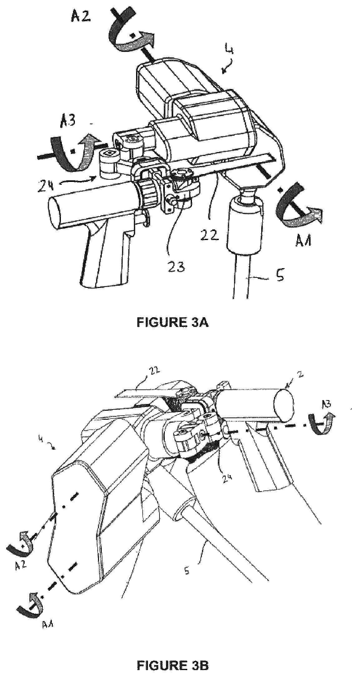
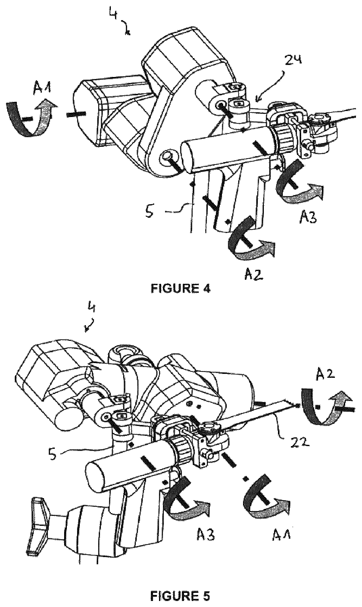
The invention relates to a surgical system for cutting an anatomical structure (F, T) of a patient according to at least one target plane defined in a coordinate system of the anatomical structure, comprising: (i) a robotic device (100) comprising: —a cutting tool, —an actuation unit (4) having a serial architecture comprising from three to five motorized degrees of freedom, at least two of said motorized degrees of freedom being rotational degrees of freedom about respective rotation axes that are substantially orthogonal to each other, configured for adjusting a position and orientation of the cutting tool relative to each target plane, —a planar mechanism connecting the last segment of the actuation unit to the cutting tool; (ii) a passive articulated lockable holding arm (5) supporting the actuation unit (4); (iii) a tracking unit (200) configured to determine in real time the pose of the cutting plane with respect to the coordinate system of the anatomical structure, (iv) a control unit (300) configured to determine the pose of the cutting plane with respect to the target plane and to control the actuation unit so as to bring the cutting plane into alignment with the target plane.

Description

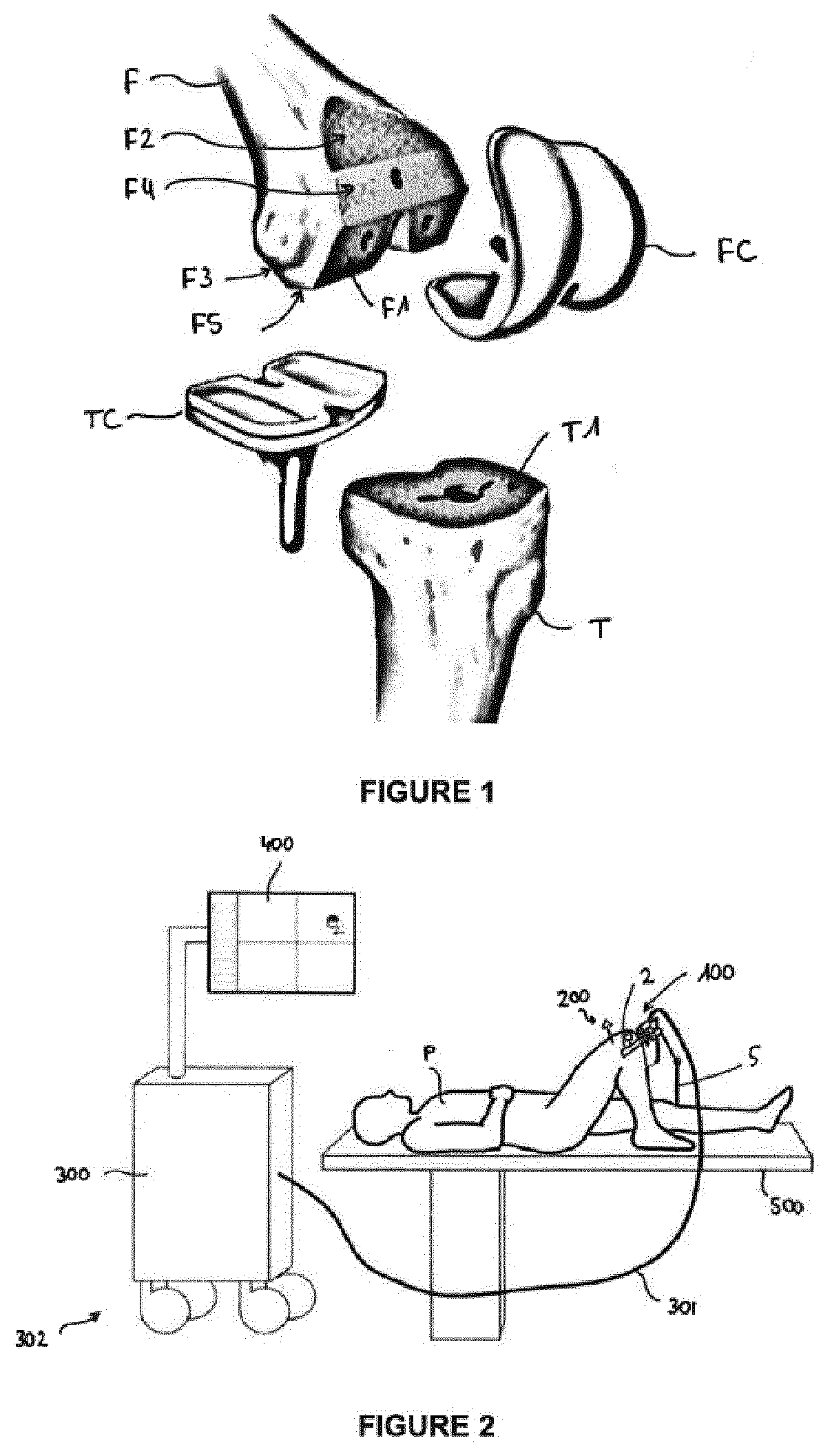
FIELD OF THE INVENTION[0001]The invention relates to a robotic system for cutting an anatomical structure of a patient according to at least one target plane.BACKGROUND OF THE INVENTION[0002]Total knee arthroplasty typically requires cutting both the femoral epiphysis and tibial epiphysis in order to remove the damaged bone and cartilage and install a knee prosthesis.[0003]To that end, a surgeon has to carry out five or more cuts on the femur and one or more cuts on the tibia by using an oscillating saw through cutting blocks.[0004]FIG. 1 is a schematic perspective view of a knee intended to receive a knee prosthesis including a femoral component FC and a tibial component TC. Generally, the cuts to be made on the femur F are: a distal cut along plane F1, an anterior cut along plane F2, a posterior cut along plane F3, and anterior and posterior chamfers F4, F5 connecting the distal plane and the anterior, respectively posterior, plane. A cut has to be made on the tibia T along plane ...

Claims


Application Information

Patent Timeline
Patent Type & Authority Applications(United States)
IPC IPC(8): A61B17/17A61B17/14A61B17/3203A61B17/3211A61B18/20A61B34/30A61B17/16
CPCA61B17/1764A61B17/142A61B17/3203A61B2018/00565A61B18/20A61B34/30A61B17/1675A61B17/3211A61B17/155A61B17/157A61B34/70A61B34/25A61B90/11A61B2090/508A61B34/20A61B2034/2055A61B2034/2059A61B17/02A61B2034/104A61B2034/2048A61B2034/2051A61B17/154A61B2018/00601
Inventor LAVALLEE, STÉPHANEDEMANGET, NICOLASCOLLET, HERVÉGIRARDEAU-MONTAUT, DANIELCHABANAS, LAURENCEURVOY, FRANÇOIS
Owner ORTHOTAXY SAS
Learn More