Combustion apparatus

Active Publication Date: 2021-11-04
HARRIS MULTI JET BURNER LTD
View PDF0 Cites 0 Cited by
  • Summary
  • Abstract
  • Description
  • Claims
  • Application Information

AI Technical Summary

Benefits of technology

This patent describes an apparatus for processing materials using an auger and a blower. The apparatus has a chamber with multiple side walls, which allows for more efficient use of the auger. The blower can be connected to either end of the auger, with the hottest end being preferred for better performance. The apparatus helps to dry the incoming feed material by heating up the gas inside the auger and feeding it through the chamber. Overall, the apparatus improves the processing of materials.

Problems solved by technology

For example fragmented interior car parts can be burnt which (even if particulated) would normally coat the inside of the conventional combustors and prevent them from working properly.

Method used


Image

  • Combustion apparatus
  • Combustion apparatus
  • Combustion apparatus

Examples


Embodiment Construction

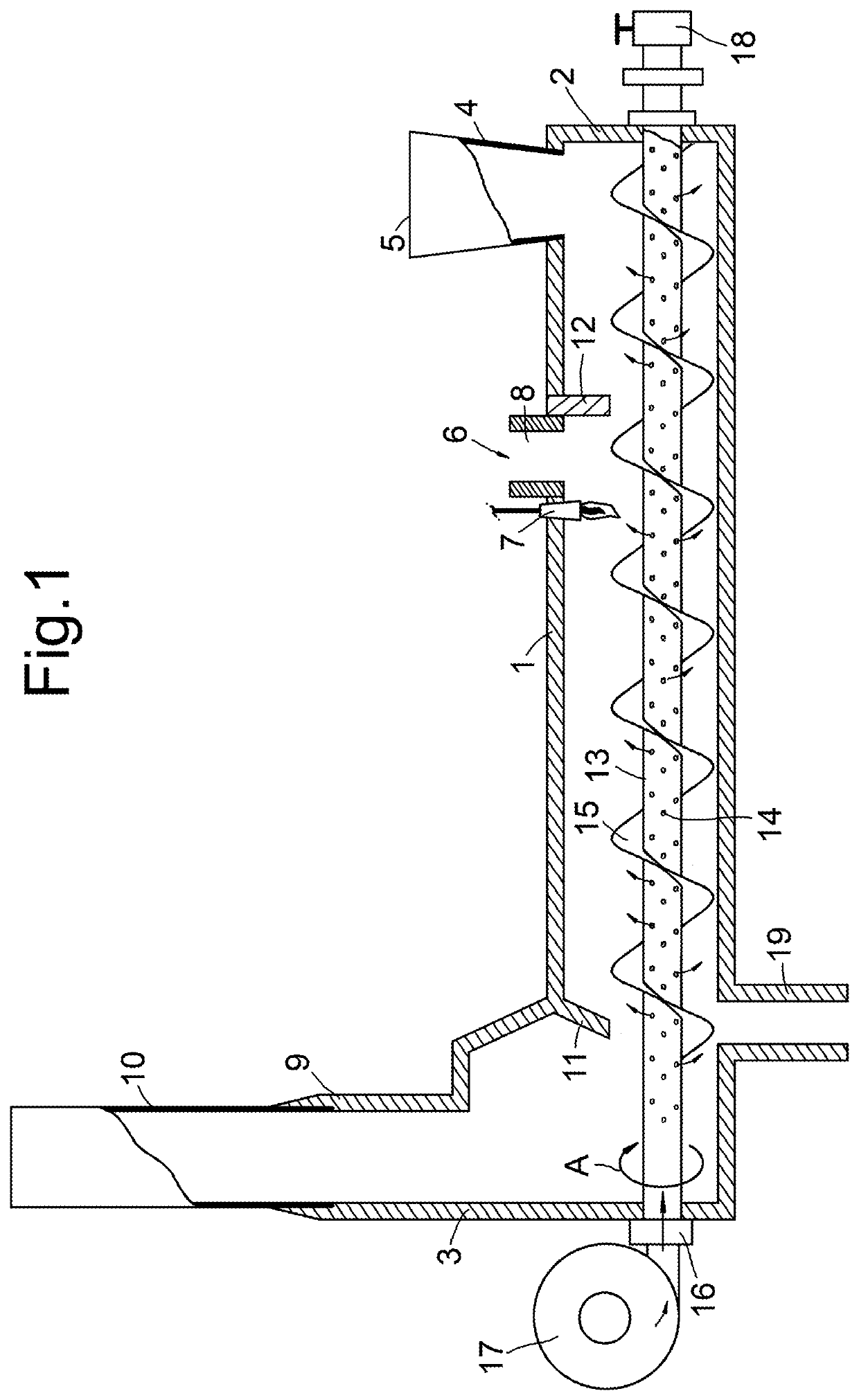
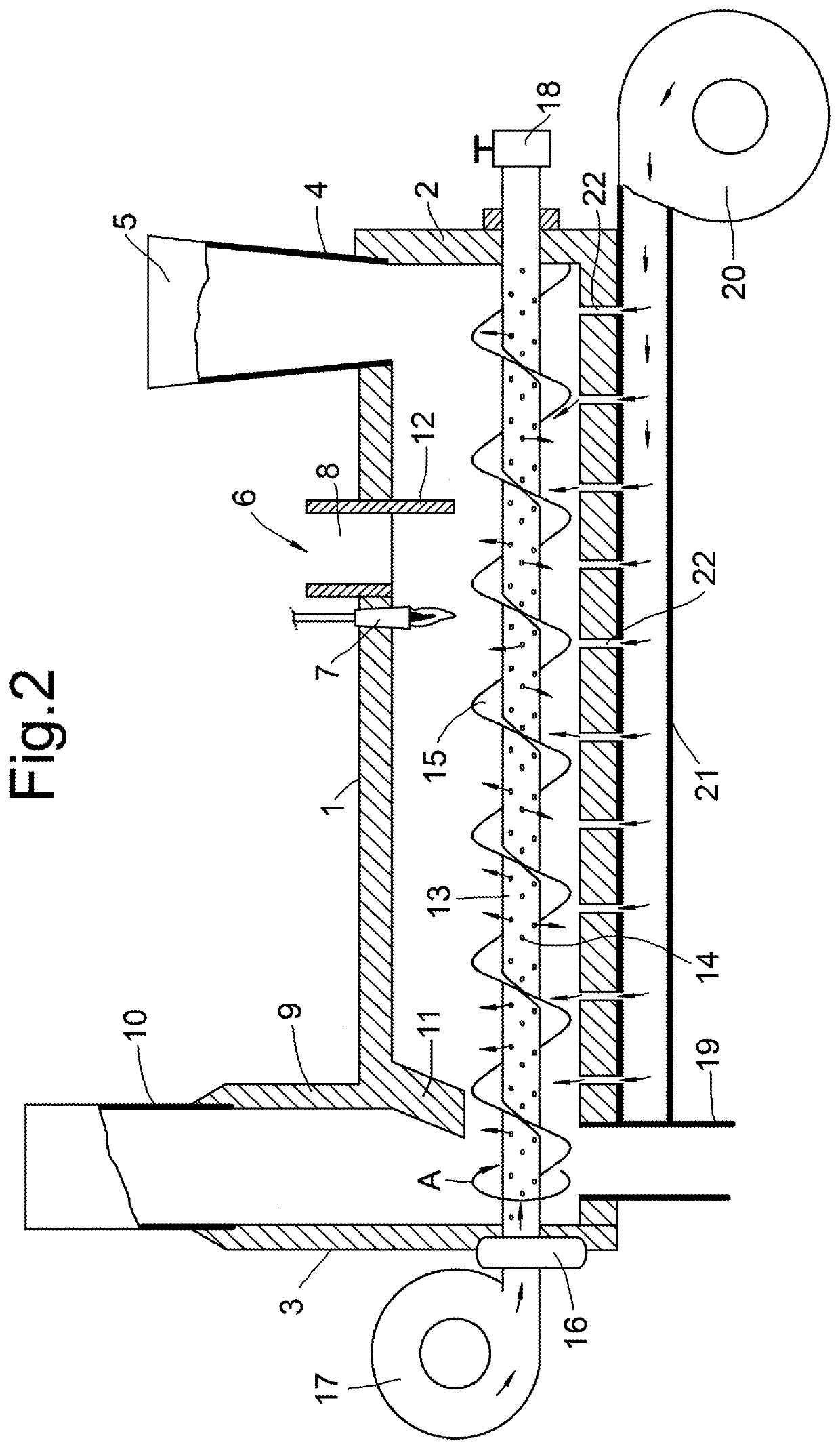
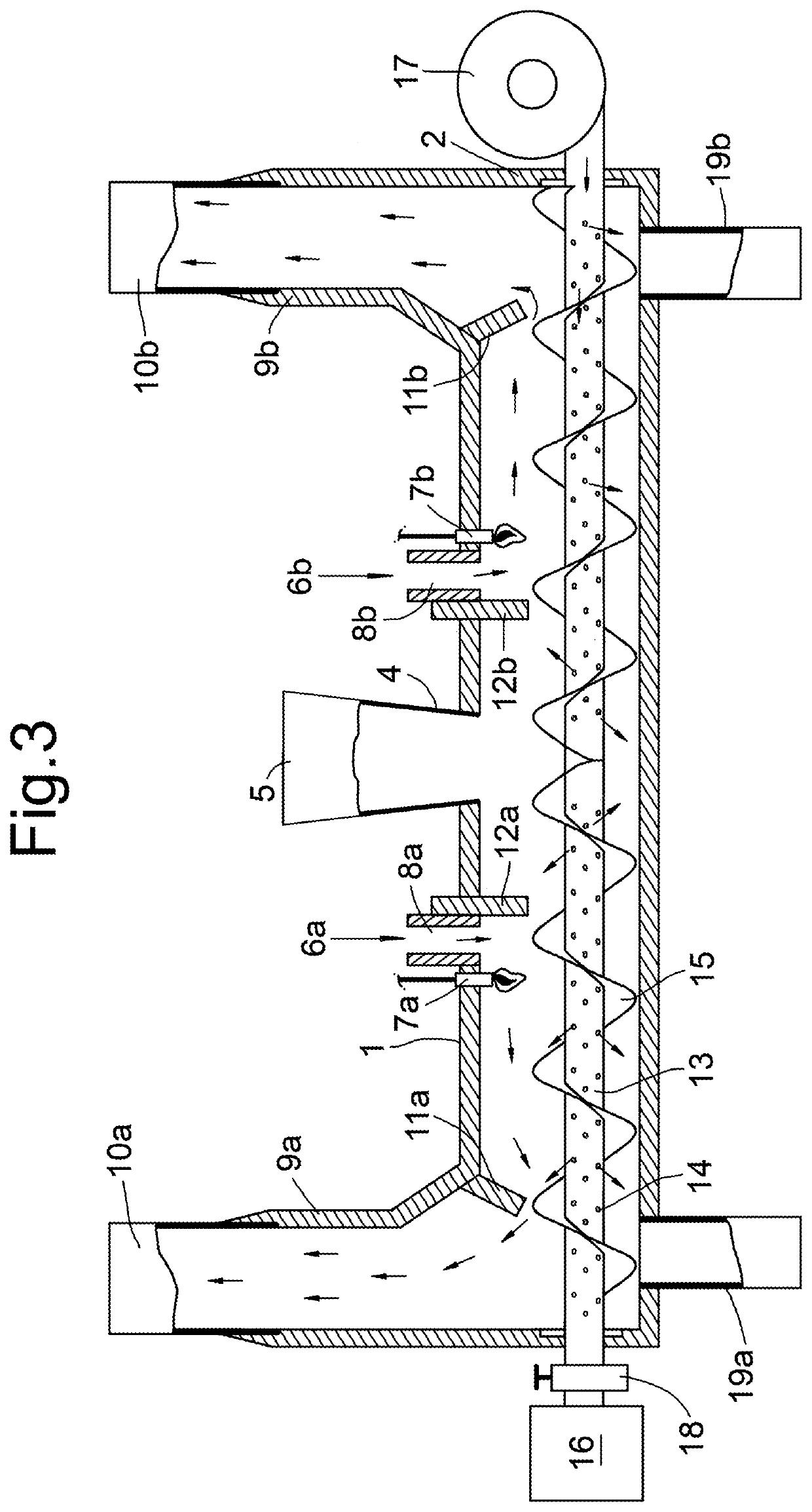
[0039]The combustion apparatus (as shown in FIG. 1) comprises a tubular combustion chamber 1, suitably formed of steel lined with refractory material such as a refractory cement. Thermal insulation material may also be incorporated to minimise heat losses from the chamber. The chamber has four side walls and first and second end walls 2 and 3. The top wall of the chamber 1 has a feed inlet 4, which in the example shown in FIG. 1 is proximal the first end wall 2. The feed inlet 4 comprises a hopper 5 for receiving combustible material. The wall of the chamber 1 also has an ignition means 6 which comprises an ignitor 7, an oil supply (not shown) and a gas inlet 8 through the side wall of the chamber 1. Distal of the feed inlet 4 there is a combustion gas outlet 9, which is in the side wall of the chamber 1 proximal the end wall 3. The combustion gas outlet 9 comprises a flue pipe 10. The outlet 9 suitable formed of steel lined with refractory material such as refractory cement. The fl...


PUM


Abstract

Disclosed herein is a combustion apparatus which comprises a chamber having a apertured rotatable tubular auger mounted between end walls of the chamber to convey particulate material from the region of the chamber proximate the feed inlet to the combustion gas outlet and a blower connected to the opposite end of the tubular auger and configured to blow gas into the bore of the auger and out through the apertures into the chamber.

Description

FIELD OF THE INVENTION[0001]The present invention relates to a combustion apparatus suitable for combusting waste materials.BACKGROUND TO THE INVENTION[0002]The generation of waste is a great burden to society and infrastructure. Governments are being required to manage both domestic and commercial waste on massive scales in a manner that is sustainable over the long term. The task of dealing with the vast variety of materials in an efficient manner is therefore a challenging one.[0003]One of the main problems when handling domestic and commercial waste materials is the generation of toxic and / or hazardous compounds which originate from the materials themselves and / or residual compounds contained within the waste. Initial processing of these materials liberates these compounds and can facilitate secondary reactions which produce further harmful compounds. This problem is exemplified when handling waste construction industry fibre board. During the initial processing the fibre board ...

Claims


Application Information

Patent Timeline
IPC IPC(8): F23G5/44F23G5/12F23G5/00F23L3/00F23L9/06F23L5/02B65G33/30F23G5/50F23G5/04F23L15/00
CPCF23G5/444F23G5/12F23G5/002F23L3/00F23L9/06F23L5/02F23G2207/30F23G5/50F23G5/04F23L15/00F23G2203/8013F23G2205/121B65G33/30F23G5/00Y02E20/34F23G7/003F23G7/105F23K3/14F23K2203/202
Inventor HARRISHARRIS, JR., MICHAELHARRIS, GLENN
Owner HARRIS MULTI JET BURNER LTD
Why Eureka
Try Eureka