
Header assembly having threadless interconnection

a header assembly and threadless technology, applied in the direction of internal electrodes, transvascular endocardial electrodes, therapy, etc., can solve the problems of lead or feedthrough assembly breakage, complex connection between leads and feedthrough assemblies, risk of infection and morbidity, etc., to achieve high yield, easy manufacturing, and accurate clocking

Active Publication Date: 2021-10-21
PACESETTER INC
View PDF1 Cites 0 Cited by
  • Summary
  • Abstract
  • Description
  • Claims
  • Application Information

AI Technical Summary

Benefits of technology

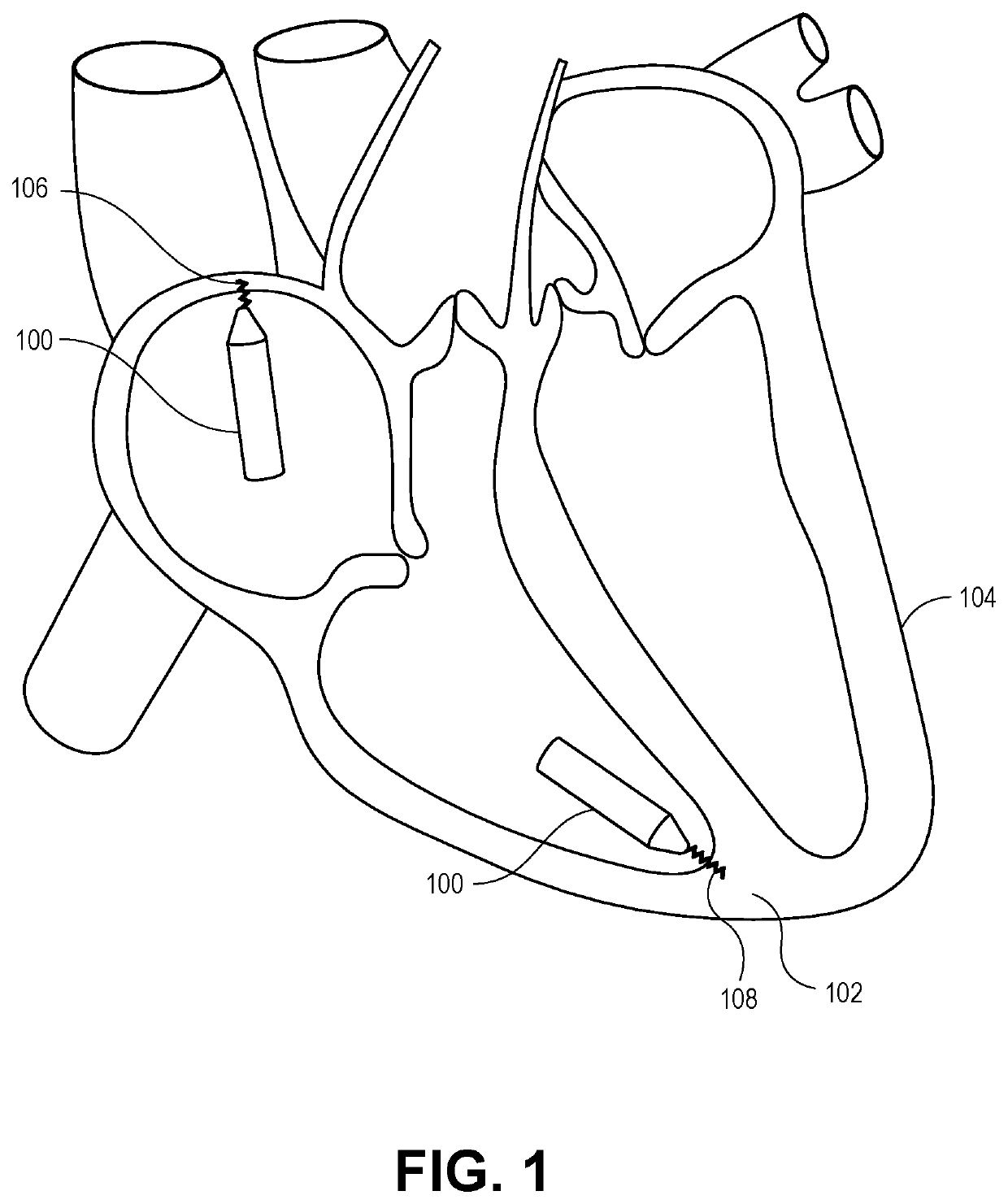
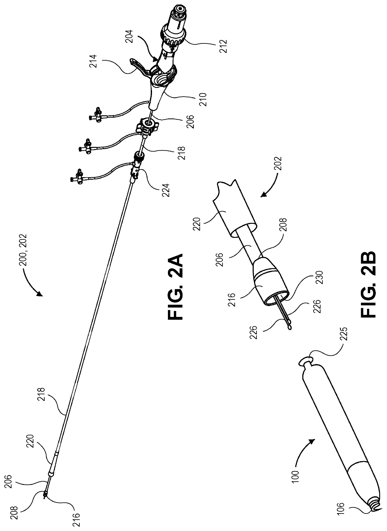
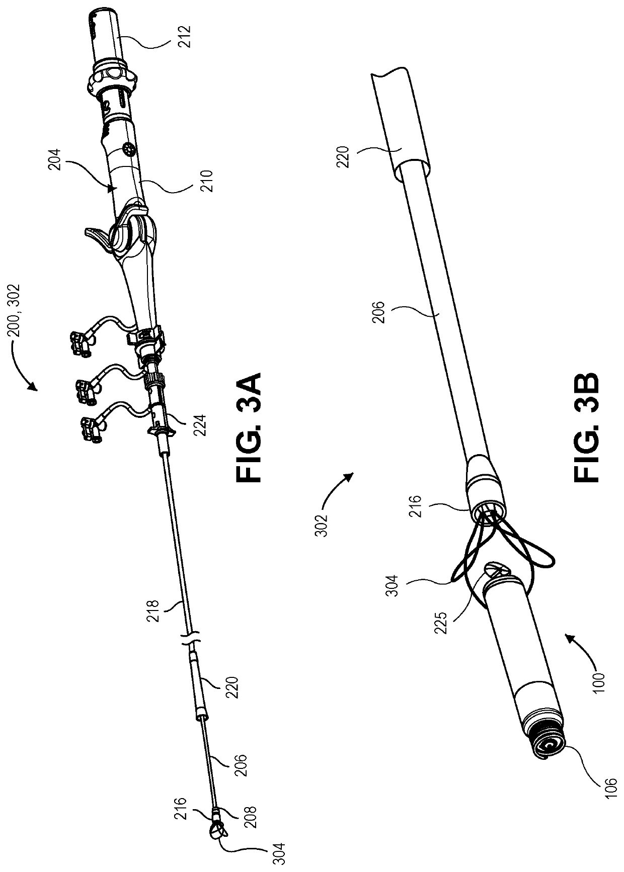
The patent describes a leadless biostimulators with a sealed device package containing internal components. The device package is supported at a target site using a fixation element, such as a fixation helix. The fixation helix is screwed onto a helix mount, which is in turn connected to a flange that contains pacing circuitry and a power source. However, existing leadless biostimulators have difficulty accurately aligning the components and may have inaccurate placement of the fixation helix, which can negatively impact tissue fixation. The patent proposes a new header assembly with a threadless interconnection between the components, providing accurate alignment and reducing manufacturing costs. The non-circular profile of the header assembly includes linear and curved segments that conform with corresponding surfaces of the helix mount, allowing for a fast, reliable manufacturing process.

Problems solved by technology

Conventional pacemakers have several drawbacks, including a risk of lead or feedthrough assembly breakage, complex connections between the leads and the feedthrough assembly, and a risk of infection and morbidity due to the separate leads and pulse generator components.
The holding thread of the helix mount and the thread of the flange are machined, which can be expensive and difficult to manufacture with high yield.
Furthermore, accurate clocking between the helix mount and the flange is difficult to control because the threaded interconnection between the components may permit relative rotation between the components or may not provide accurate rotational orientation of the components when tightly fastened.
Inaccurate alignment between the helix mount and the flange can result in inaccurate placement of the fixation helix, which can negatively impact tissue fixation.
The conforming surfaces interfere with rotation of the helix mount relative to the flange.
The protrusion can interfere with longitudinal movement of the helix mount relative to the flange.

Method used


Image

  • Header assembly having threadless interconnection
  • Header assembly having threadless interconnection
  • Header assembly having threadless interconnection

Examples


Embodiment Construction

[0030]Implementations of the present disclosure include a biostimulator, e.g., a leadless cardiac pacemaker, having a header assembly that includes a threadless interconnection between components. The biostimulator may be used to pace cardiac tissue. The biostimulator may be used in other applications, however, such as deep brain stimulation. Thus, reference to the biostimulator as being a cardiac pacemaker is not limiting.

[0031]Descriptions of various implementations of the present disclosure are made with reference to the figures. However, certain implementations may be practiced without one or more of these specific details, or in combination with other known methods and configurations. In the following description, numerous specific details are set forth, such as specific configurations, dimensions, and processes, in order to provide a thorough understanding of the example implementations. In other instances, well-known processes and manufacturing techniques have not been descri...


PUM


Abstract

A leadless biostimulator, such as a leadless cardiac pacemaker, having a header assembly is described. The header assembly includes a helix mount mounted on a flange. An inner surface of the helix mount conforms to an outer surface of the flange, and the outer surface has a non-circular profile such that the conforming surfaces interfere with rotation of the helix mount relative to the flange. The non-circular profile includes a linear segment, such as a radial segment, that resists rotational movement of the helix mount. The helix mount has a protrusion that extends into a recess of the flange to interfere with longitudinal movement between the helix mount and the flange. The protrusion is formed before or after mounting the helix mount on the flange. The interfering surfaces threadlessly interconnect the header assembly components. Other embodiments are also described and claimed.

Description

[0001]This application claims the benefit of priority of U.S. Provisional Patent Application No. 63 / 010,541, filed on Apr. 15, 2020, which is incorporated herein by reference in its entirety to provide continuity of disclosure.BACKGROUNDField[0002]The present disclosure relates to biostimulators having header assemblies. More specifically, the present disclosure relates to leadless biostimulators having header assemblies that include a helix mount interconnected with a flange, and methods of manufacturing such header assemblies.Background Information[0003]Cardiac pacing by an artificial pacemaker provides an electrical stimulation of the heart when its own natural pacemaker and / or conduction system fails to provide synchronized atrial and ventricular contractions at rates and intervals sufficient for a patient's health. Such antibradycardial pacing provides relief from symptoms and even life support for hundreds of thousands of patients. Cardiac pacing may also provide electrical ov...

Claims


Application Information

Patent Timeline
Patent Type & Authority Applications(United States)
IPC IPC(8): A61N1/375A61N1/05
CPCA61N1/37518A61N1/3756A61N2001/058A61N1/37512A61N1/0573A61N1/3752
Inventor HANSEN, JOSEPHVICTORINE, KEITHALLEMAN, WESLEY
Owner PACESETTER INC
Learn More