Shielding for probing system

a probing system and shielding technology, applied in the field of probing systems, can solve the problems of reducing the accuracy of the testing of the semiconductor device, difficult or in fact technically impossible to shield such a large shielding chamber by the probing system, and difficulty in maintaining consistency for the semiconductor wafer

Active Publication Date: 2021-10-07
TECAT TECH (SUZHOU) LTD
View PDF0 Cites 1 Cited by
  • Summary
  • Abstract
  • Description
  • Claims
  • Application Information

AI Technical Summary

Benefits of technology

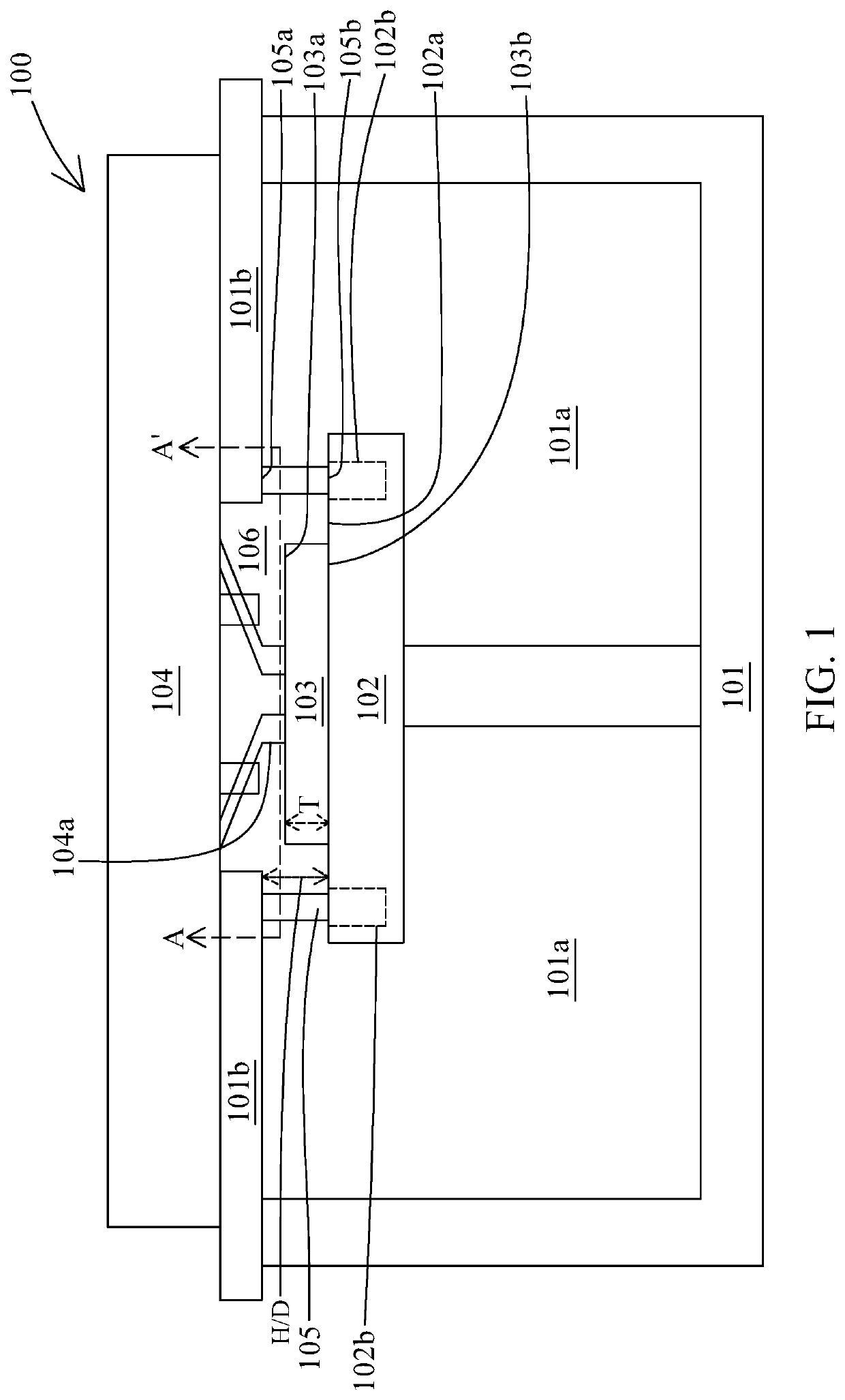
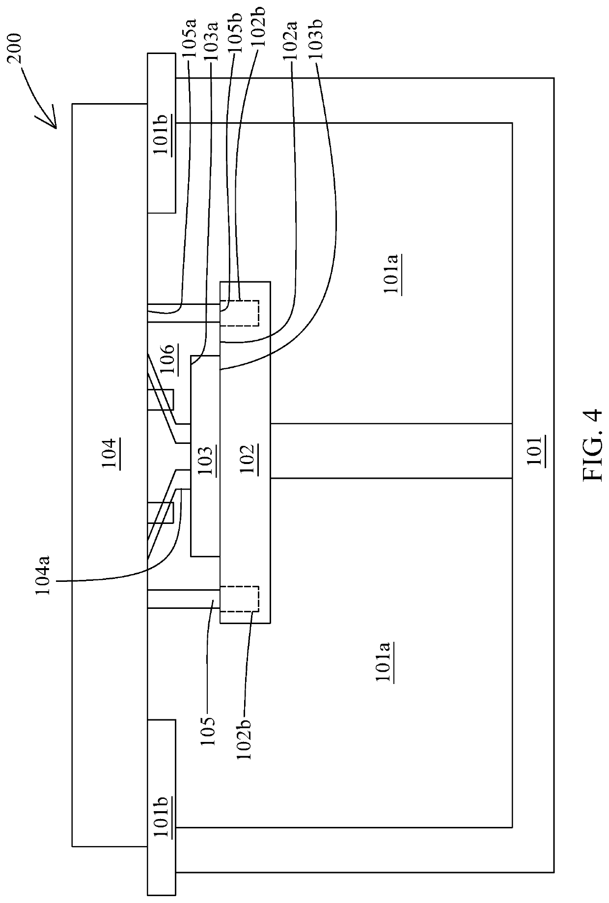
[0010]In some embodiments, the shielding member is in contact with the platen to provide complete isolation of the DUT with the surrounding environment.
[0013]In some embodiments, a height of the shielding member is substantially greater than a thickness of the DUT wafer ensuring sufficient clearance between the wafer and the platen.
[0017]In some embodiments, a cover enclosing the probe card or probe manipulator ensures complete shielding of the DUT from the surrounding environment.

Problems solved by technology

However, such specific conditions may be difficult to maintain consistency for the semiconductor wafer during the testing or probing.
Therefore, accuracy of the testing of the semiconductor device may be decreased.
However, it is very difficult or in fact technically impossible to shield such a large shielding chamber by the probing system.
Although a space of such shielding chamber is smaller than the one for the whole probing system, it is still difficult to securely shield the chuck and the semiconductor wafer.
Testing under different environment is difficult to achieve with existing probing system or may require high gas flow, equipment requiring high energy consumption, use of high-volume gas, etc. to fill up or purge the environment of the probing system with large chamber.

Method used


Image

  • Shielding for probing system
  • Shielding for probing system
  • Shielding for probing system

Examples


Embodiment Construction

[0035]The following description of the disclosure accompanies drawings, which are incorporated in and constitute a part of this specification, and illustrate embodiments of the disclosure, but the disclosure is not limited to the embodiments. In addition, the following embodiments can be properly integrated to complete another embodiment.

[0036]References to “one embodiment,”“an embodiment,”“exemplary embodiment,”“other embodiments,”“another embodiment,” etc. indicate that the embodiment(s) of the disclosure so described may include a particular feature, structure, or characteristic, but not every embodiment necessarily includes the particular feature, structure, or characteristic. Further, repeated use of the phrase “in the embodiment” does not necessarily refer to the same embodiment, although it may.

[0037]In order to make the present disclosure completely comprehensible, detailed steps and structures are provided in the following description. Obviously, implementation of the prese...


PUM


Abstract

A probing system includes a chuck configured to support a device under test (DUT); a probe card disposed above the chuck and including a plurality of probes protruding from the probe card toward the chuck; and a platen disposed between the chuck and the probe card and configured to support the probe card, wherein the chuck includes a shielding member disposed between the platen and the chuck.

Description

TECHNICAL FIELD[0001]The present disclosure relates to a probing system including a chuck configured to support a device under test (DUT) thereon, and particularly relates to the chuck having a shielding member extendable from the circumferential fixture of the chuck, disposed in the chuck or being part of the chuck and surrounding the DUT. Further, the present disclosure relates to a method of operating the probing system for probing the DUT disposed on a chuck, and particularly relates to a method of probing the DUT surrounded by the shielding member extendable from and the chuck, disposed in the chuck or being part of the chuck under wide varying temperature, pressure, humidity, or gas filled environment. This shielding member of the chuck minimizes the volume space of the chamber required for purging with dry air, gases or any environment required for testing.DISCUSSION OF THE BACKGROUND[0002]After fabrication, a semiconductor device, such as a wafer, is tested by a probing syst...

Claims


Application Information

Patent Timeline
Patent Type & Authority Applications(United States)
IPC IPC(8): G01R31/28G01R1/067
CPCG01R31/2886G01R31/2865G01R1/06755G01R1/18G01R31/2601G01R31/2881G01R31/2874G01R31/2831
Inventor LOU, CHOON LEONG
Owner TECAT TECH (SUZHOU) LTD
Why Eureka
Try Eureka