Gas Turbine Combustor and Method of Manufacturing Burner Component
a technology of gas turbine combustor and burner component, which is applied in the direction of turbines, machines/engines, light and heating apparatus, etc., can solve the problems of reduced relative density of materials, increased cost, and time taken for lamination, and achieves cost advantage and high environmental performance.
- Summary
- Abstract
- Description
- Claims
- Application Information
AI Technical Summary
Benefits of technology
Problems solved by technology
Method used
Image
Examples
first embodiment
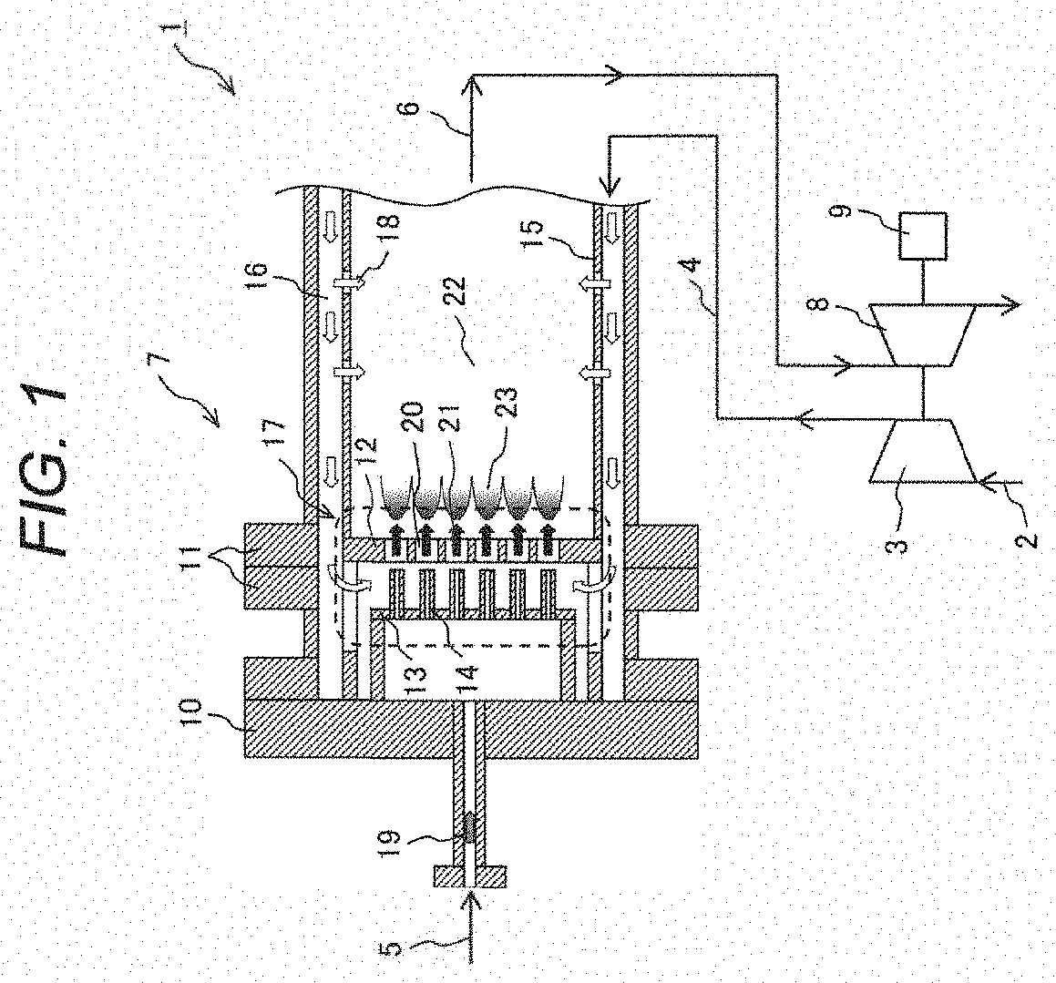
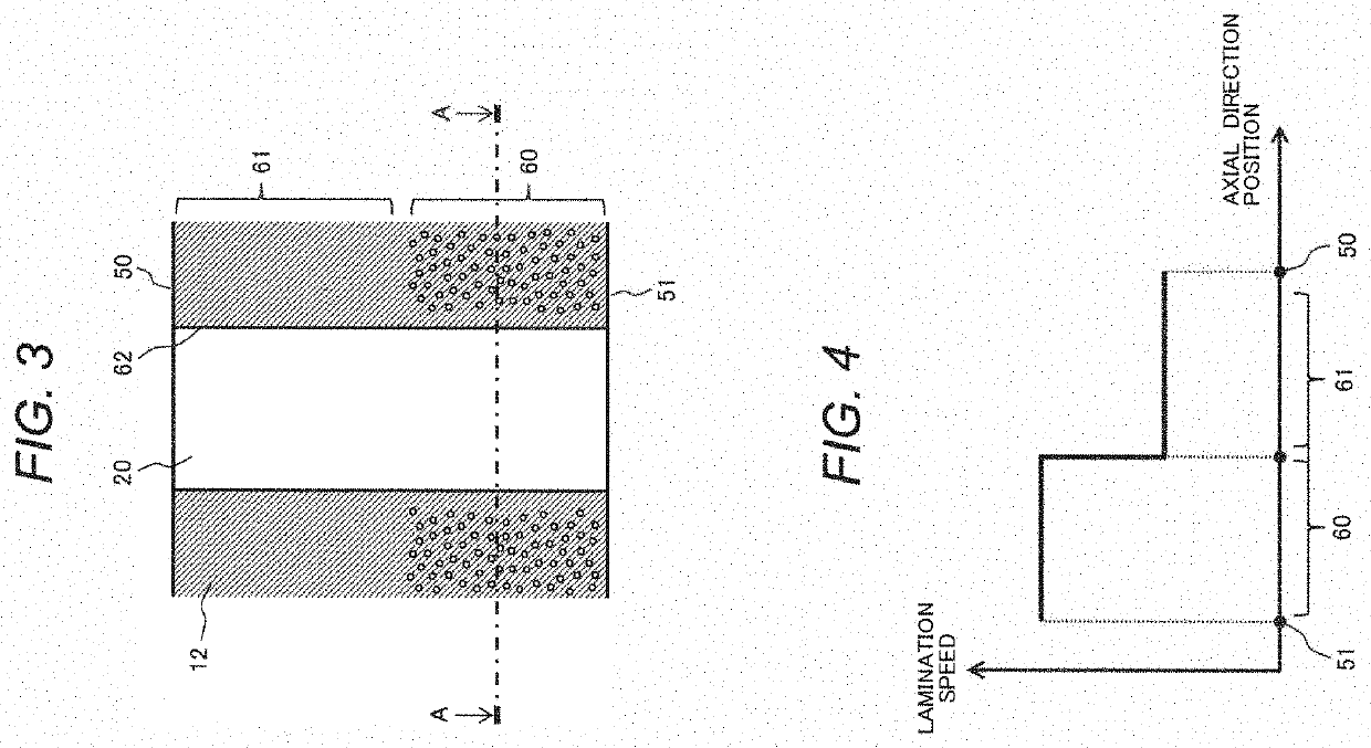
[0036]Next, a structure and a manufacturing method of a burner component according to the first embodiment of the present invention will be described with reference to FIG. 3 and FIG. 4. In the first embodiment, the perforated plate 12 will be described as one example of the burner component.
[0037]FIG. 3 illustrates one example of one metal material relative density distribution on the perforated plate 12 in the first embodiment. FIG. 3 is an enlarged diagram illustrating one example of a part 54 of the perforated plate 12 which is illustrated in FIG. 2. Since a downstream-side end face 50 of the perforated plate 12 is heated with radiant heat and so forth of the flames 23, a region 61 which is close to the downstream-side end face 50 of the perforated plate 12 reaches a high temperature. On the other hand, an upstream-side end face 51 of the perforated plate 12 and an inner face 62 of each nozzle hole 20 are cooled with the compressed air 4 and therefore become lower in temperature...
second embodiment
[0049]A structure and a manufacturing method of the burner component according to the second embodiment of the present invention will be described with reference to FIG. 5 and FIG. 6. In the second embodiment, the perforated plate 12 will be described as one example of the burner component similarly to the first embodiment.
[0050]FIG. 5 illustrates one example of another metal material relative density distribution of the perforated plate 12 in the second embodiment. FIG. 5 is a diagram in which a lamination speed transition region 70 is added to the diagram in FIG. 3. In the manufacturing method according to the first embodiment in FIG. 4, the lamination speeds of the region 60 and the region 61 are mutually switched discontinuously. However, in a case where discontinuous switching of the lamination speeds is impossible due to control of a manufacturing device or in a case where the material strength is reduced by discontinuous switching of the lamination speeds, it is possible to d...
third embodiment
[0052]A structure and a manufacturing method of the burner component according to the third embodiment of the present invention will be described with reference to FIG. 7. In the third embodiment, the perforated plate 12 will be described as one example of the burner component similarly to the first embodiment and the second embodiment.
[0053]FIG. 7 illustrates one example of still another metal material relative density distribution on a part 80 which is adjacent to the inner face 62 of each nozzle hole 20 in the perforated plate 12 in the third embodiment. In addition, FIG. 7 is a sectional diagram taken along the A-A line in FIG. 3 or FIG. 5. Since the inner face 62 of each nozzle hole 20 is cooled with the compressed air 4, thermal stress generates in the adjacent part 80 of the inner face 62 of each nozzle hole 20.
[0054]Accordingly, in the third embodiment, the perforated plate 12 is manufactured in such a manner that the lamination speed of the metal material on the adjacent pa...
PUM
| Property | Measurement | Unit |
|---|---|---|
| temperature | aaaaa | aaaaa |
| temperature | aaaaa | aaaaa |
| temperature | aaaaa | aaaaa |
Abstract
Description
Claims
Application Information
 - R&D
- Intellectual Property
- Life Sciences
- Materials
- Tech Scout
- Unparalleled Data Quality
- Higher Quality Content
- 60% Fewer Hallucinations
Browse by: Latest US Patents, China's latest patents, Technical Efficacy Thesaurus, Application Domain, Technology Topic, Popular Technical Reports.
© 2025 PatSnap. All rights reserved.Legal|Privacy policy|Modern Slavery Act Transparency Statement|Sitemap|About US| Contact US: help@patsnap.com


