
Waterproof structure of connector

a technology of connectors and water-reinforced connectors, which is applied in the direction of couplings/cases, coupling device connections, electrical devices, etc., can solve the problems of affecting the waterproof performance, difficult to reduce the length dimension, and difficult to implement a small diameter of rubber plugs and even a small diameter of connectors. achieve the effect of ensuring waterproof performance and small siz

Active Publication Date: 2021-09-23
AUTONETWORKS TECH LTD +3
View PDF0 Cites 1 Cited by
  • Summary
  • Abstract
  • Description
  • Claims
  • Application Information

AI Technical Summary

Benefits of technology

This patent text describes a connector housing for a multicore cable that is designed to have excellent waterproof performance while also being small in size. The technical effects of this invention include the fact that the waterproof member collectively waterproofs an area from the connector main body to the outer sheath of the cable, so there is no need to stop the opening of the tip of the outer sheath with the waterproof member. Additionally, there is no need to interpose the waterproof member between the wires, which decreases the diameter of the connector. Furthermore, the lip portion of the waterproof member follows deformation of the cable, which further improves the waterproof performance. Overall, this patent text presents a solution for providing a connector housing that guarantees a proper waterproofing without being affected by the posture of the wire in the outer sheath and offers greater efficiency, reliability, and durability for use in various applications.

Problems solved by technology

However, in this configuration, in a case where an inserted wire deviates from the predetermined posture (angle), a shape followability of the rubber plug is insufficient and thus a gap may be generated between the wire and the rubber plug to impair a waterproof performance.
For this reason, in a case where, particularly, a wire with a relatively large diameter is bent in the connector, it is difficult to decrease the length dimension.
Furthermore, since a rubber is interposed between the respective wires, it is difficult to implement a small diameter of the rubber plug and even a small diameter of the connector.
Therefore, in a case where the power wire is bent between the tip of the outer sheath and the connector main body, the bent portion is liable to affect even the tip of the outer sheath and it is thus difficult to fit a posture (angle) of the wire to the waterproof member at the tip of the outer sheath.

Method used


Image

  • Waterproof structure of connector
  • Waterproof structure of connector
  • Waterproof structure of connector

Examples


embodiment 1

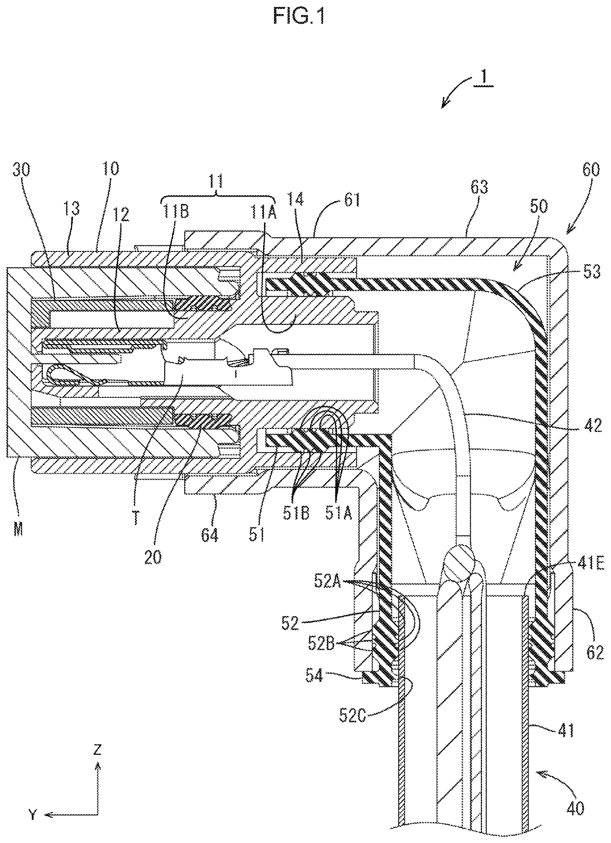
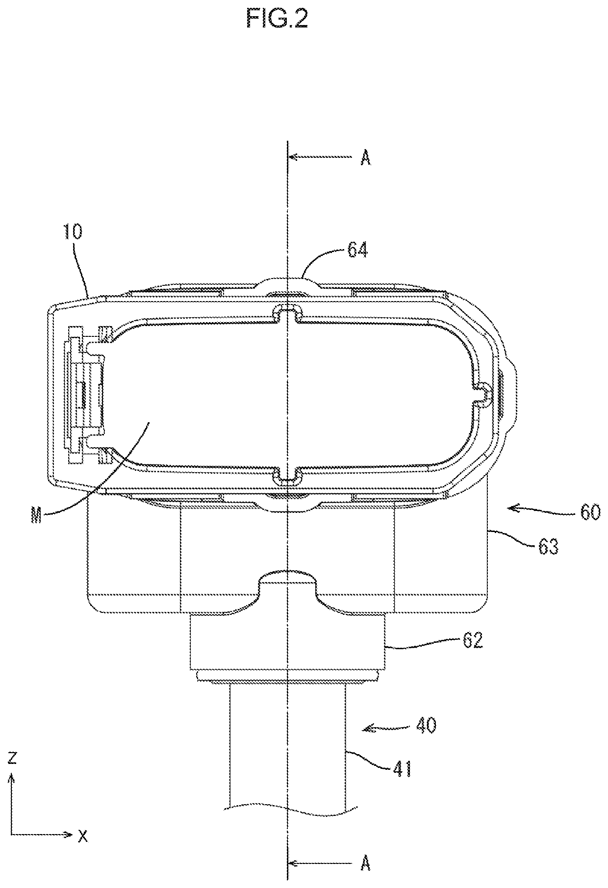
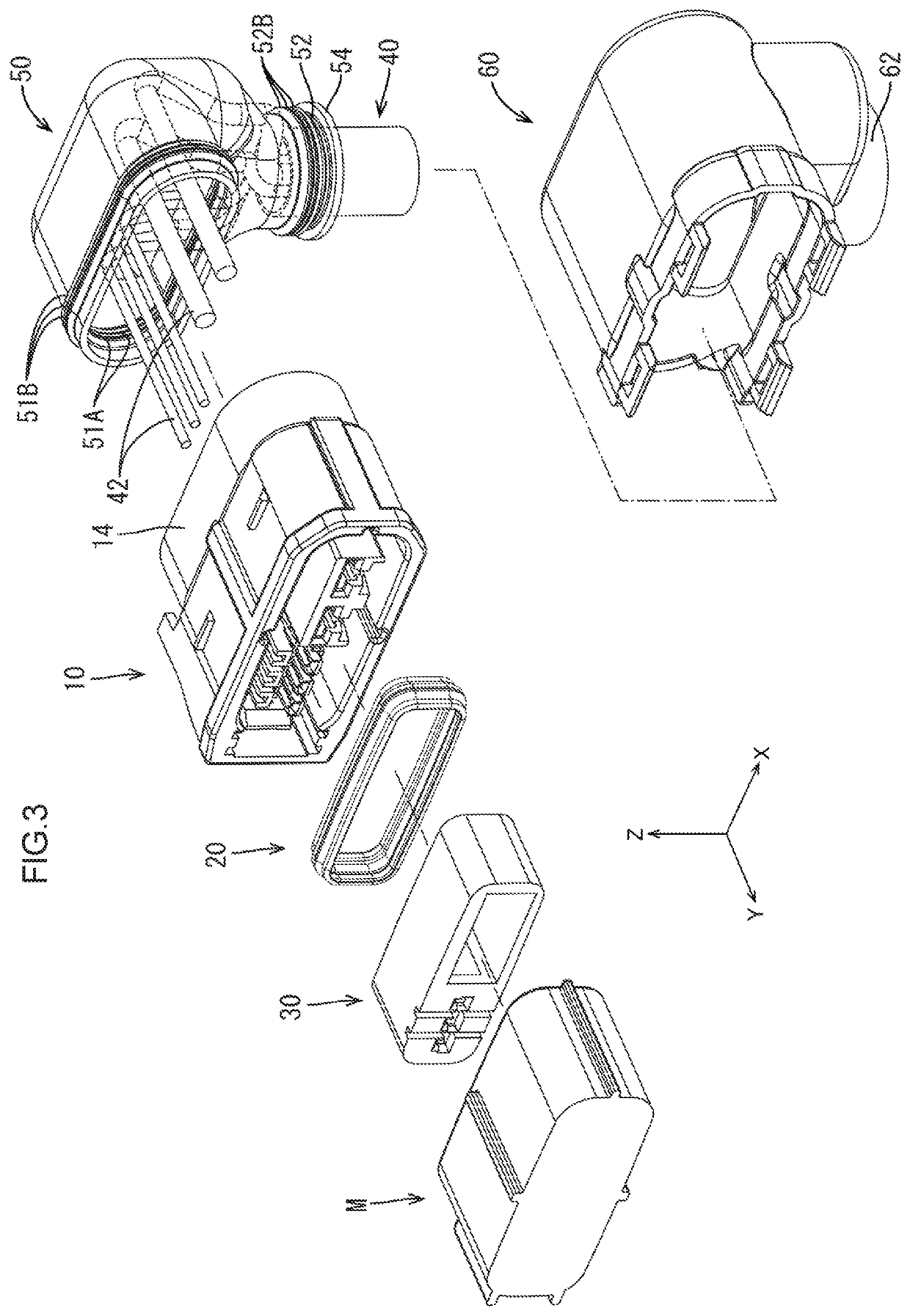
[0029]Embodiment 1 of the technology disclosed in the present description will be described with reference to FIGS. 1 to 8. Note that in the following description, an X direction, a Y direction, and a Z direction in the drawings indicate the right side, the front side, and the top side, respectively. Furthermore, in the following description, only one of the same plurality of members has a reference symbol and reference symbols of the others are omitted in some cases.

[0030]A connector 1 according to the present embodiment is used by being connected to a tip of a cable 40 (an example of a multicore cable) disposed in a tire house of a vehicle and extending from a power supply in, for example, an electric braking system, and being fitted with a counterpart connector M attached to an electronic control unit (ECU) for controlling braking.

[0031]As illustrated in FIG. 1, the connector 1 includes a connector housing 10 (an example of a connector main body), a cable 40 (an example of a mult...

embodiment 2

[0050]Next, Embodiment 2 of the technology disclosed in the present description will be described with reference to FIGS. 9 and 10.

[0051]Unlike Embodiment 1, in a connector 100 of the present embodiment, an outer cylinder portion 14 in a connector housing 110 is omitted and two first tie band positioning protrusions 155 are circumferentially provided on a seal member 150 over the whole circumference, instead of an auxiliary connector seal portion 51B. Further, a tie band 170 is disposed between the two first tie band positioning protrusions 155 for fastening to increase adhesion of a connector fitting portion 151 with respect to an inner cylinder portion 111A of a wire surrounding portion 111. The cover member 160 is provided with a tie band disturbance preventing portion 160A at substantially the center of a front end portion of an upper surface thereof, such that a tie band fastening portion 170A is not disturbed when the cover member 160 is fitted onto the connector housing 110.

[...


PUM


Abstract

A waterproof structure of a connector 1 is configured to waterproof a cable 40 including a sheath 41 surrounding a plurality of wires 42, and a connector housing 10 connected to the plurality of wires 42 extending from a tip portion 41E of the sheath 41. The waterproof structure includes a seal member 50 collectively covering the plurality of wires 42 between the cable 40 and the connector housing 10. The seal member 50 has one end fitted onto the sheath 41 and in which the plurality of wires 42 extend from the tip portion 41E with any arrangement relation, and another end fitted into the connector housing 10.

Description

BACKGROUNDField of the Invention[0001]The present invention relates to a waterproof structure of a connector attached to a tip of a wire conductive portion.Related Art[0002]As a waterproof structure of a connector in which a plurality of wires are led into and connected to a housing, a technology disclosed in Japanese Unexamined Patent Application Publication No. 2013-97898 has been known. In this technology, in order to prevent an intrusion of water or the like into an outer sheath in which the plurality of wires are bundled together, a rubber plug is fitted onto a tip (a led-out portion of the wires) of the outer sheath and the wires are individually inserted through a plurality of through holes provided in the rubber plug in a predetermined posture (at a predetermined angle), respectively, thereby stopping an opening (a gap between each wire and the outer sheath) of the tip of the outer sheath.[0003]However, in this configuration, in a case where an inserted wire deviates from th...

Claims


Application Information

Patent Timeline
Patent Type & Authority Applications(United States)
IPC IPC(8): H01R13/52H01R13/523
CPCH01R13/5205H01R13/5213H01R13/523H01R13/56H01R9/03H01R13/502
Inventor KOMORI, HIROKAZUNAKAGAWA, YUSUKE
Owner AUTONETWORKS TECH LTD
Learn More