Method and device for extruding and labelling a cylindrical product

a technology of cylindrical products and packaging tubes, applied in the direction of coatings, etc., can solve the problems of reduced flexibility of the manufacturing process, reduced production rate, and increased complexity of the process, and achieve the effects of facilitating the extrusion of resin grades, enhancing productivity, and increasing production ra

Active Publication Date: 2021-09-23
AISAPACK HLDG SA
View PDF0 Cites 0 Cited by
  • Summary
  • Abstract
  • Description
  • Claims
  • Application Information

AI Technical Summary

Benefits of technology

[0075]Another advantage of the invention is to facilitate the extrusion of grades of resins that are difficult to extrude because of generating “stick and slip” phenomena during calibration or of generating surface defects or again of generating breaks in the extrudate.
[0076]More generally, the invention may be used to enhance productivity because the molten material is no longer in direct contact with the surface of the calibration element. The rubbing of the molten material on the calibration element encountered in a conventional extrusion process is eliminated and so the production rate can be increased.
[0077]The packaging resulting from this manufacturing process offers very high cohesion between the label and the tubular body. The risks of the label becoming unstuck during the use of the packaging are avoided in contrast to prior art packaging produced with an adhesive label. Another advantage is linked to the absence of discontinuity on the surface of the tubular body, which makes it possible to prevent the discomforts linked to labels the edge surfaces of which can accumulate dust and degrade the esthetic properties.
[0078]The invention further enables production of decorated tubes of small or large diameter. It offers very great flexibility, and can be used in new installations or enables the modification of existing extrusion installations.
[0079]The invention also consists in an extrusion-labeling device as defined in the claims. The device produced in accordance with one preferred embodiment comprises means for extrusion of a tubular body in the molten state; a vacuum calibration and cooling tank; means for driving the cooled tube; cutting or rolling means and means for unrolling a film; a swan-neck shaper disposed between the extrusion head and the vacuum calibration tank; means for exerting a first pressure difference between the interior and the exterior of the extruded tubular body; means for exerting a second pressure difference between the interior and the exterior of the tube when it enters the vacuum calibration tank.
[0080]The label preferably passes through a swan-neck shaper disposed between the extrusion nozzle and the calibration element. Thanks to the swan-neck shaper, the label does not enter the extrusion tools, which prevents damage to the decorative film. In the present invention, the swan-neck shaper enables the extrusion tools to be extended into the interior of the tubular geometry formed by the film. The use of a swan-neck shaper is advantageous for a number of reasons. It prevents contact between the film and the hot tools, and by virtue of its compactness it enables reduction of the length of the tool referred to as the nozzle which is extended inside the swan-neck. The head losses and consequently the pressures generated by the flow of the molten material in the tooling are greatly reduced.

Problems solved by technology

This printing operation has a number of disadvantages linked to the fact that the printing is not carried out flat but on the tubular geometry of the skirt.
This generally leads to a process of greater complexity and consequently costly equipment, lower production rates, and reduced flexibility of the manufacturing process.
The lack of flexibility of printing machines leads for example to reworking operations for complex decorations such as screenprinting or a hot decoration process.
The addition of an adhesive layer by coating at the moment of application of the label or the addition of an activation step makes the manufacturing process more complex, in particular when applied on a line for continuous tube extrusion (FIG. 2 of WO 2007 / 092652).
Another disadvantage lies in the very short activation time of the adhesive layer that this method requires, which can lead to a restricted and costly choice of adhesives.
Another disadvantage is situated at the level of the packaging: the label that is added to the surface of the tube is not an integral part of the wall of the packaging.
The edges of the label are sometimes visible or detectable by touch and compromise the decorative and esthetic properties of the packaging.
A first disadvantage is linked to the fact that the liner must be extruded inside the tubular body formed by the film.
The method proposed in this prior art does not enable the production of tubes of small diameter and in particular of tubes with a diameter less than 35 mm.
Apart from the issues of bulk cited above, this method has the disadvantage of generating small variations of the outside diameter of the tube.
These variations, which depend on the regularity of the throughput of the extruder, can generate decoration defects.
These variations generate visual defects at the level of the junction of the edges of the decorative film.
Similar disadvantages are found in the methods and devices described in the patent applications DE 1 504 918 and DE 10 2006 006 993 for example.

Method used


Image

  • Method and device for extruding and labelling a cylindrical product
  • Method and device for extruding and labelling a cylindrical product
  • Method and device for extruding and labelling a cylindrical product

Examples


Embodiment Construction

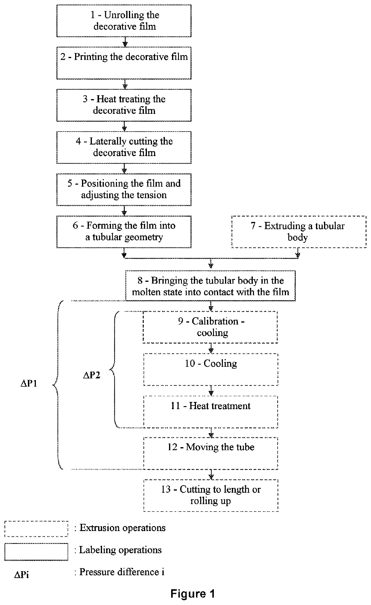
[0095]FIG. 1 shows one embodiment of the method of the invention in the form of a block diagram representing the steps of the method.

[0096]In a first step (1), a decorative film (that will form the label) is unrolled from a spool, which is the usual method of producing decorative films of this kind for tubes of this kind.

[0097]In the method according to the invention, there follows the second step (2), which may be optional, in which is notably effected an operation of printing the decorative film. The decorative film can be printed using any of the known flat printing methods such as for example (nonlimiting): flexography, screenprinting, heliogravure, typographic printing, offset printing, hot stamping, cold foil, or again digital printing and combinations of these printing technologies. The invention will advantageously be associated with digital printing for productions necessitating flexibility and rapid changes of decoration. The printing may also be covered by a protective va...


PUM

PropertyMeasurementUnit
melting pointaaaaaaaaaa
diameteraaaaaaaaaa
temperatureaaaaaaaaaa

Abstract

The method for extruding and labeling a packaging tube comprises the following successive steps:
    • a) forming a partially or totally tubular label from a film in a shaper; b) inserting the label into a calibration element; c) extruding a tubular body at the concave-face side of the label in an extrusion head; d) bringing the outer face of the extruded tubular body into contact with the concave face of the label. In the method, the label comprises at least one layer of which the melting temperature is at least 20° C. higher than the melting temperature of the extruded tubular body. A first pressure difference is formed in the extruded tube with an air jet.
The invention also relates to a device for implementing said method and to a tube obtained by said method.

Description

CORRESPONDING APPLICATION[0001]The present application claims the priority of the earlier European application No. EP16188491.1 filed 13 Sep. 2016 in the name of AISAPACK HOLDING S.A., the content of that earlier application being incorporated by reference in its entirety into the present application.TECHNICAL FIELD AND PRIOR ART[0002]The invention is situated in the field of tubes or cylinders, and more particularly in the field of packaging tubes for liquid or viscous products, such as toothpastes and creams, the skirt of which is obtained by extrusion of material.[0003]Flexible packaging tubes generally have two distinct parts, namely a flexible cylindrical body or skirt connected to a head including a neck that is closed by a cap. The skirt of the tube is obtained either by extrusion of a tubular body or by welding of a multilayer film that is rolled up to form this tubular body before welding it edge to edge or with an overlap.[0004]A number of methods exist for adding and fixi...

Claims


Application Information

Patent Timeline
Patent Type & Authority Applications(United States)
IPC IPC(8): B29C48/00B29C48/09B29C48/14B29C48/90B29C48/152
CPCB29C48/0021B29C48/0023B29C48/901B29C48/141B29C48/09B29C63/065B29C48/152B29C48/278B29C48/902Y02P70/10B29C48/14B29C48/15
Inventor THOMASSET, JACQUESREY, EDUARDO
Owner AISAPACK HLDG SA
Why Eureka
Try Eureka