
Material testing of optical test pieces

a technology for optical test pieces and material testing, applied in the direction of optical apparatus testing, image enhancement, instruments, etc., can solve the problems of comparatively complex manual visual inspection, disadvantages and limitations of reference techniques, and defects that may arise during the production of optical elements

Active Publication Date: 2021-09-09
CARL ZEISS JENA GMBH
View PDF4 Cites 3 Cited by
  • Summary
  • Abstract
  • Description
  • Claims
  • Application Information

AI Technical Summary

Benefits of technology

The patent text describes a need for improved techniques for material testing of optical test objects using optical detection. The technical effect of the patent is to provide techniques that eliminate or alleviate limitations of current techniques and improve the accuracy and reliability of material testing. The use of angle-variable illumination and detection allows for tailored contrast and automated assessment of test object quality, reducing measurement time.

Problems solved by technology

Various defects may arise during the production of optical elements—such as lenses.
However, such reference techniques have certain disadvantages and limitations.
By way of example, a manual visual inspection can be comparatively complex.
Moreover, obtaining a quantitative quality value may not be possible or only possible to a limited extent.
By way of example, it may often be complicated and complex to obtain a sufficiently large number of images for carrying out a reconstruction of the test object.
In addition, corresponding techniques can be time-intensive and susceptible to errors.

Method used


Image

  • Material testing of optical test pieces
  • Material testing of optical test pieces
  • Material testing of optical test pieces

Examples


Embodiment Construction

b class="d_n">[0057]The properties, features and advantages of this invention described above and the way in which they are achieved will become clearer and more clearly understood in association with the following description of the exemplary embodiments which are explained in greater detail in association with the drawings.

[0058]The present invention is explained in greater detail below on the basis of preferred embodiments with reference to the drawings. In the figures, identical reference signs denote identical or similar elements. The figures are schematic representations of different embodiments of the invention. Elements illustrated in the figures are not necessarily illustrated as true to scale. Rather, the various elements illustrated in the figures are rendered in such a way that their function and general purpose become comprehensible to the person skilled in the art. Connections and couplings between functional units and elements as illustrated in the figures can also be...


PUM


Abstract

The invention relates to techniques for material testing of optical test pieces, for example of lenses. Angle-variable illumination, using a suitable illumination module, and / or angle-variable detection are carried out in order to create a digital contrast. The digital contrast can be, for example, a digital phase contrast. A defect detection algorithm for automated material testing based on a result image with digital contrast can be used. For example, an artificial neural network can be used.

Description

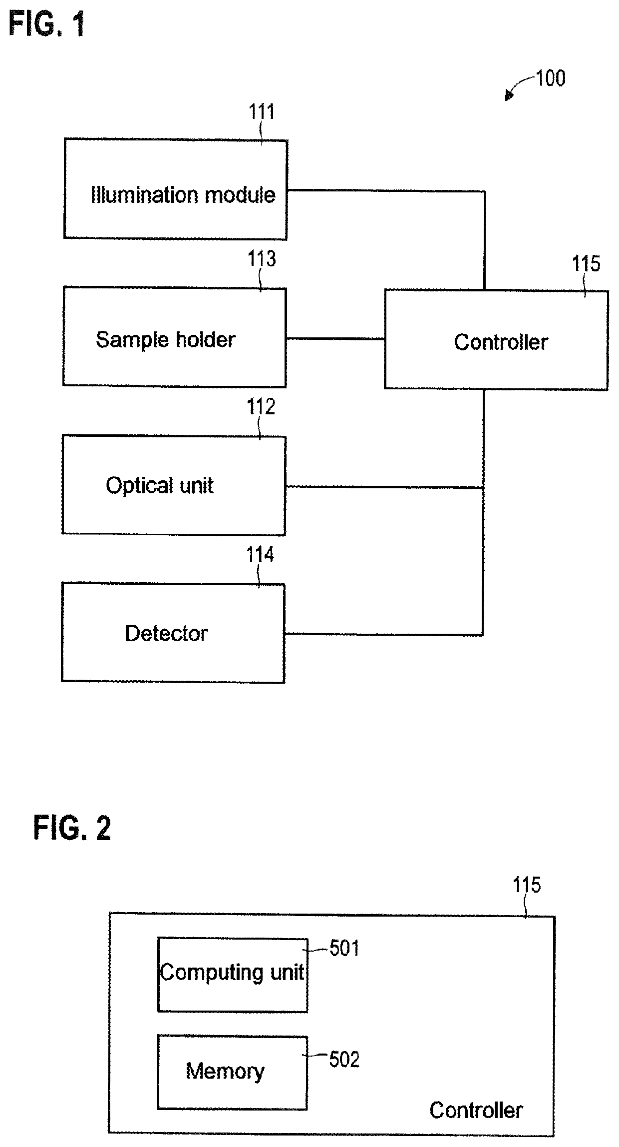
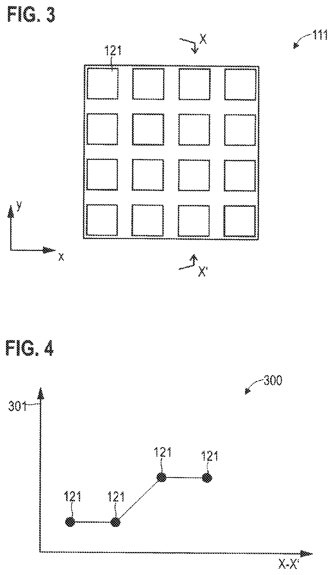
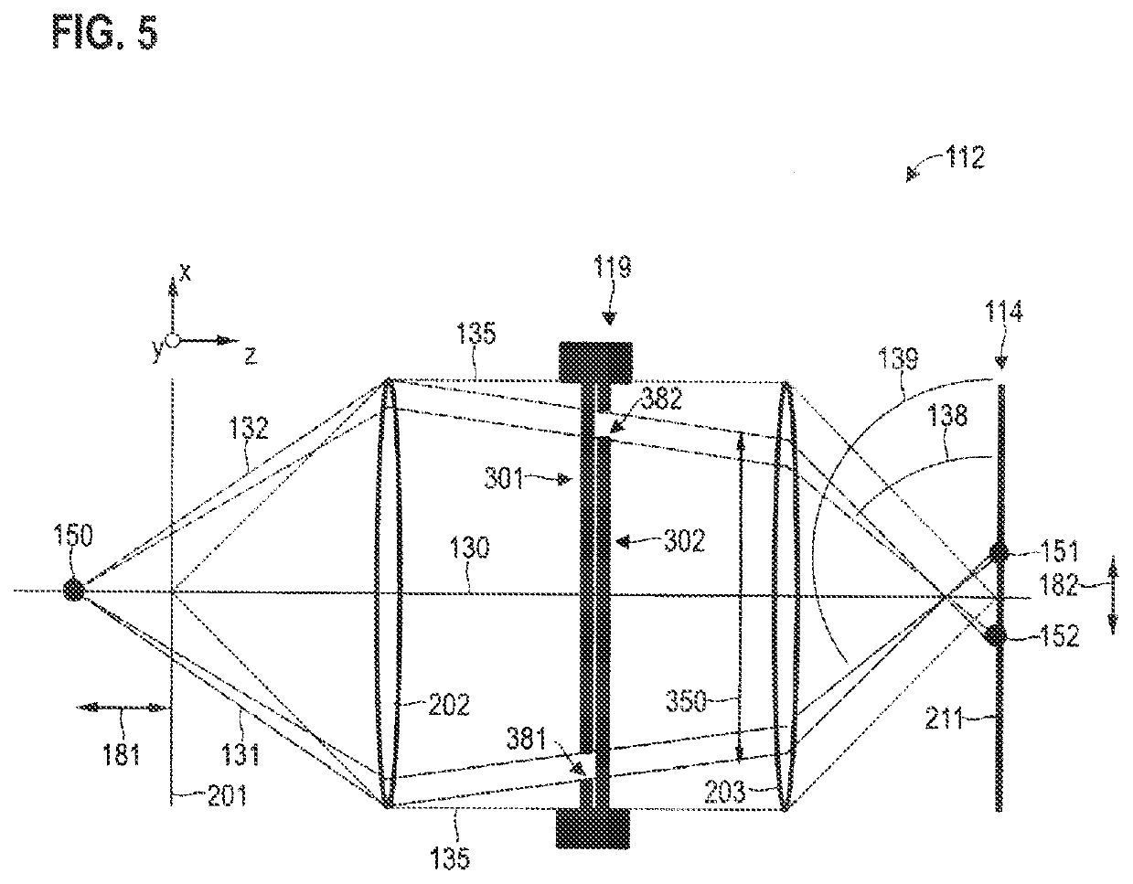
TECHNICAL FIELD[0001]In general, various embodiments of the invention relate to techniques for material testing of optical test objects. In particular, the various embodiments of the invention relate to techniques for material testing of optical test objects using angle-variable illumination and / or angle-variable detection.BACKGROUND[0002]Various defects may arise during the production of optical elements—such as lenses. Examples of defects include: scratches; inclusions; material defects; matt surfaces; streaks; flaking; bore errors; optical offset; and turning marks.[0003]Conventionally, optical elements, as test objects, are subjected to a manual visual examination by experts, Typically, special lamps are used in the process in order to make the defects visible. A further technique is the so-called “shape from shading” technique for reconstructing the surfaces in the reflection mode. For instance, the “shape from shading” (SFS) technique is described in Prados, Emmanuel, and Oliv...

Claims


Application Information

Patent Timeline
Patent Type & Authority Applications(United States)
IPC IPC(8): G06T7/00G06T7/70G06T5/50G06T5/00G01M11/02
CPCG06T7/0004G06T7/70G06T5/50G06T5/007G06T2207/10152G01M11/0221G01M11/0264G06T2207/20084G06T2207/20081G01M11/0278G06T5/90
Inventor STOPPE, LARSMEVENKAMP, NIKLASFREYTAG, ALEXANDER
Owner CARL ZEISS JENA GMBH
Learn More