Electrical cable connecting system

Pending Publication Date: 2021-08-05
MARK DAVID CROSIER
View PDF4 Cites 0 Cited by
  • Summary
  • Abstract
  • Description
  • Claims
  • Application Information

AI Technical Summary

Benefits of technology

The cable protector has a slidable cover that can be opened and closed to protect the wires. The cover can slide back and forth to allow the wires to be extended or covered. The cover has features that guide the protector in the correct position when connected to a connector. The technical effect of this invention is to provide a safe and easy way to handle building electrical cables.

Problems solved by technology

Installing electrical wiring and electrical and electronic wiring devices, including, but not limited to, receptacles, switches, wired spur connectors, Transient Voltage Surge Suppressors (TVSS), Ground Fault Circuit Interrupters (GFCI), Arc Fault Circuit Interrupters (AFCI), dimmers, thermostats, timer devices, and sensors or similar devices, in and around industrial, commercial and residential buildings is a very labor-intensive process.
For large-scale installations, the need for skilled electricians results in a significant financial cost to the contractor and ultimately the building owner or occupier.
However, proper safety procedures are not always adhered to, and the power source is not always turned off, thereby creating a hazardous environment for the person that is working on the electrical wiring and / or the electrical or electronic wiring devices.
Such situations may arise due to a lack of care or knowledge of the status of the power source, or because the person performing the electrical work does not know which circuit breaker should be turned off, or because the building occupier does not want the rest of the circuits connected to the circuit breaker turned off while the work proceeds (live working).

Method used


Image

  • Electrical cable connecting system
  • Electrical cable connecting system
  • Electrical cable connecting system

Examples


Embodiment Construction

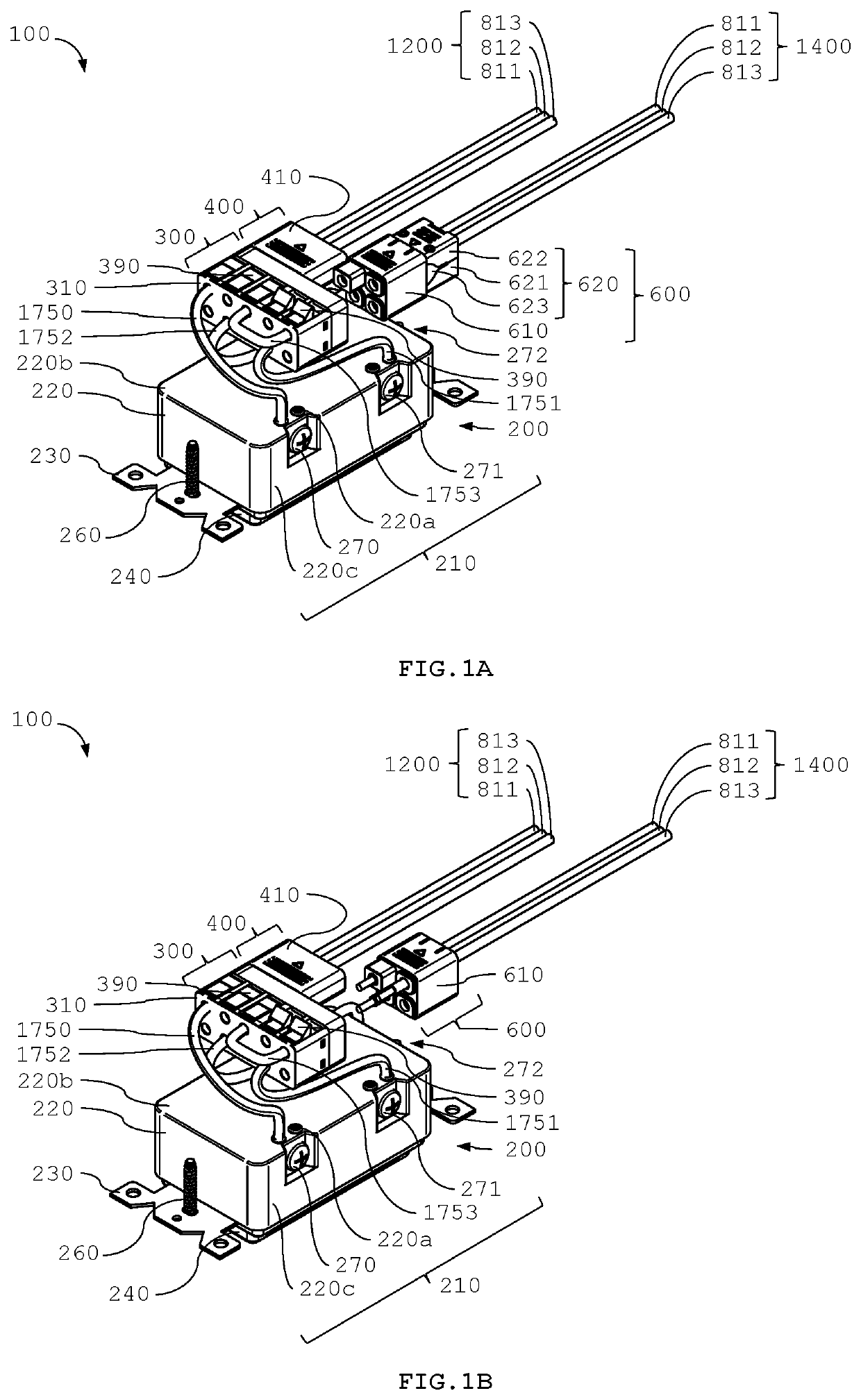
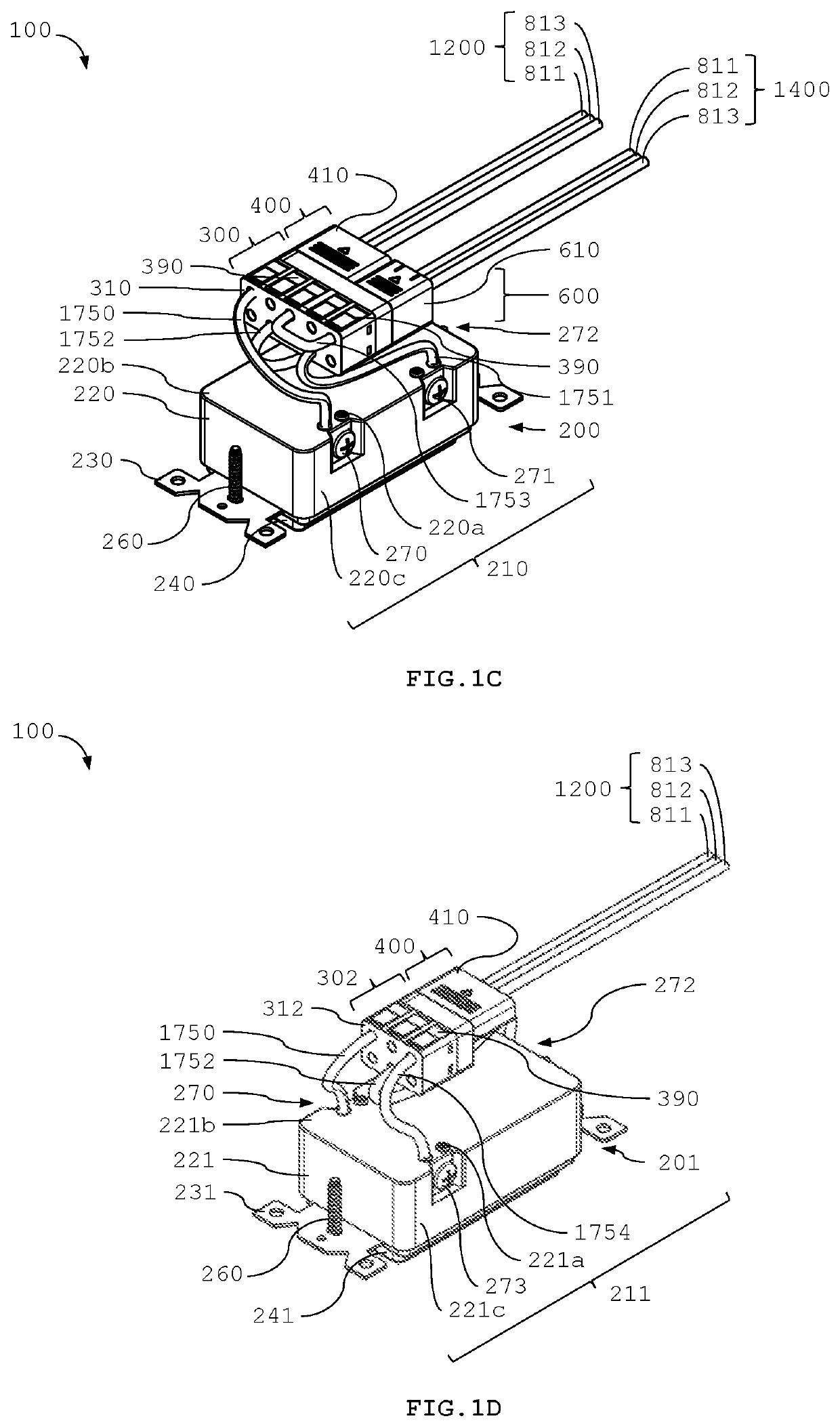
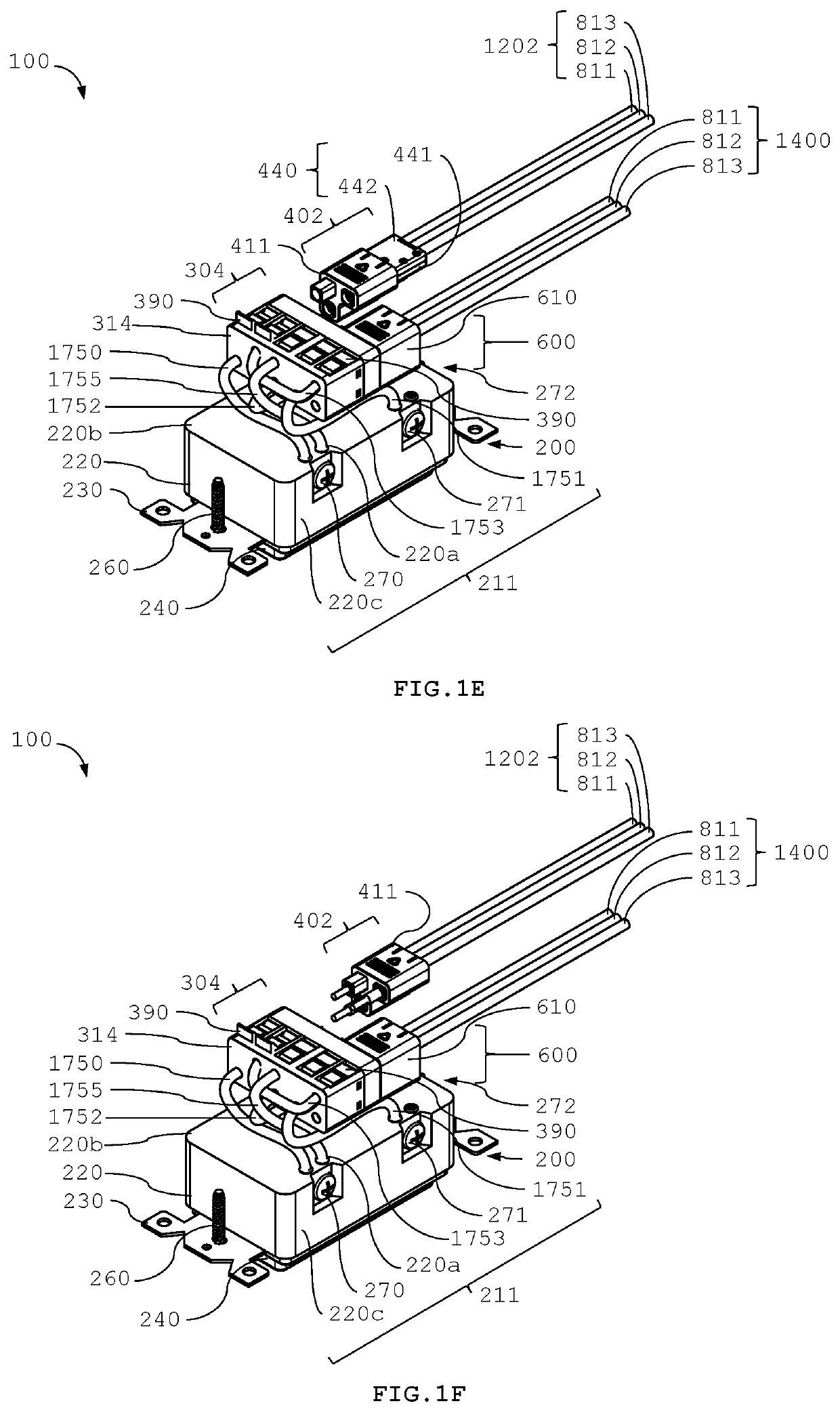
[0136]Reference will now be made in detail to exemplary embodiments of the present invention, examples of which are illustrated in the accompanying drawings. Like reference numerals as used herein refer to like or corresponding, but not necessarily identical, elements throughout. In certain instances, like reference numerals may refer to like elements which may not be identical; for example, they may not be identically positioned, and may not be identically configured, in various specific figures, in which circumstances the differences between these generally like elements is apparent from the description herein and figures (see, for example, FIGS. 2A, 2C, and 2F, wherein terminal ports referenced therein (350-359, 350-355, and 350-359 respectively) refer to connector terminal ports which may be different in location and characteristics). Also, while describing exemplary embodiments referenced herein, detailed descriptions about related functions or configurations that may diminish ...


PUM


Abstract

An electrical cable connecting system includes a modular electrical or electronic wiring device assembly, in which an electrical or electronic wiring device and a connector may be electrically coupled via pig-tail jumper electrical wires. The connector may be coupled to cable electrical wires fitted with a cable protector to protect the electrical wire conductors therein. The connector may include internal electrical terminals for electrically coupling building electrical cable wires with corresponding jumper electrical wires. The connector may be mechanically and electrically coupled to and directly terminate one or more building electrical cables, which may provide power to or from one or more electrical or electronic wiring devices by establishing an electrical pathway from a source of electrical power, through the building electrical cable wires, the connector, the pig-tail jumper electrical wires and an electrical or electronic wiring device.

Description

CROSS-REFERENCE TO RELATED APPLICATION[0001]This application claims the benefit of priority to U.S. Provisional Patent Application No. 62 / 969,042 filed on Feb. 1, 2020, the entire contents of which are incorporated herein by reference.TECHNICAL FIELD[0002]The present invention comprises an electrical cable connecting system and components thereof, for use in industrial, commercial and residential building wiring infrastructure and other applications. More particularly, but not exclusively, the present invention comprises a connecting system for use in industrial, commercial and residential building wiring infrastructure that enables pre-cut and factory terminated building electrical cables to be installed and connected to suitably adapted electrical or electronic wiring devices using substantially less field installation labor than present systems.BACKGROUND[0003]Installing electrical wiring and electrical and electronic wiring devices, including, but not limited to, receptacles, sw...

Claims


Application Information

Patent Timeline
IPC IPC(8): H01R4/48H01R13/627H01R4/22H01R25/00H02G3/18
CPCH01R4/4818H01R13/6271H02G3/18H01R25/003H01R25/006H01R4/22H01R13/4538H01R13/025H01R13/64H01R13/5045H01R24/78H01R11/09H01R4/48365H01R4/48185
Inventor CROSIER, MARK DAVID
Owner MARK DAVID CROSIER
Why Eureka
Try Eureka