Optical device field of view cleaning apparatus

a cleaning apparatus and optical device technology, applied in the field of keeping the field of view of optical devices, can solve the problems of inability to work, contamination may become visible on the image, image loss, etc., and achieve the effect of ensuring the optical transparency of the main cylinder and preventing damage to the main cylinder

Active Publication Date: 2021-07-22
MONOMER SOFTWARE LLC
View PDF0 Cites 4 Cited by
  • Summary
  • Abstract
  • Description
  • Claims
  • Application Information

AI Technical Summary

Benefits of technology

[0015]In yet another form, the instant invention main cylinder and the sacrificial transparent film rotation mechanism provides a path which ensures the sacrificial transparent film is always

Problems solved by technology

Such contaminants are undesired since they impair the optical path of the optical device, in other words, the contaminants cause the received or projected image to lose its optical fidelity, and the contaminants may become visible on the image.
While the housing and the transparent glass or plastic view window protects the optical device from contaminants the problem then becomes one of maintaining the cleanliness of the transparent glass or plastic view window rather than maintaining the cleanliness of the lens.
The simple solution of the prior art would be

Method used


Image

  • Optical device field of view cleaning apparatus
  • Optical device field of view cleaning apparatus
  • Optical device field of view cleaning apparatus

Examples


Embodiment Construction

[0029]The instant invention utilizes the terms non-sacrificial transparent main cylinder and transparent main cylinder interchangeably.

[0030]The term front refers to the direction in which the camera lens or optical path is facing.

[0031]The instant invention uses sacrificial transparent film, transparent film and film interchangeably.

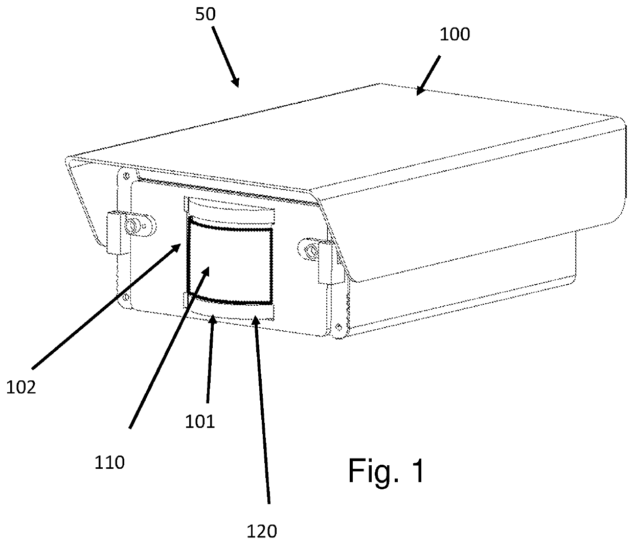
[0032]The term optical device refers to a camera capable of creating a digital representation of the objects in the field of view, a laser device used to measure or sense objects in the field of view or an infrared sensor used to sense objects in the field of view.

[0033]The term transparent film as used in the disclosure is used to describe any transparent film made from radar transparent materials, laser transparent materials, optically clear materials, Polyester, PET, Polyethylene, Polypropylene, Polyvinyl Chloride, Cellulose Acetate, Cellophane, or similar other clear material.

[0034]The terms instrument, camera, infra-red detector Lidar, Lidar and ra...


PUM


Abstract

The invention relates to a method and apparatus for keeping the field of view of an optical device (camera, laser, etc.) clean and unobstructed from dirt, contaminants, dust, chemicals, or other physical or chemical obstructions that hinder the performance of the optical device and, more particularly it employs a sacrificial transparent film positioned in front of and radially around a transparent main cylinder, within which an optical device is to be located.

Description

CROSS-REFERENCE TO RELATED APPLICATION[0001]This application claims priority from U.S. Provisional Patent Application No. 62 / 963,321, filed Jan. 20, 2020, titled SELF-CLEANING CAMERA APPARATUS which is hereby incorporated by reference herein for all purposes.COPYRIGHT STATEMENT[0002]A portion of the disclosure of this patent document contains material that is subject to copyright protection. The copyright owner has no objection to the facsimile reproduction by anyone of the patent document or the patent disclosure as it appears in the Patent and Trademark Office patent file or records, but otherwise reserves all copyright rights whatsoever.[0003]Trademarks used in the disclosure of the invention and the applicants make no claim to any trademarks referenced.BACKGROUND OF THE INVENTION1) Field of the Invention[0004]The invention relates to a method and apparatus for keeping the field of view of an optical device (camera, laser, etc.) clean and unobstructed from dirt, contaminants, dus...

Claims


Application Information

Patent Timeline
IPC IPC(8): H04N5/225
CPCH04N5/22521H04N5/2252H04N5/2254H04N23/52H04N23/51H04N23/55
Inventor HELMRICH, HARRY J.
Owner MONOMER SOFTWARE LLC
Why Eureka
Try Eureka