Semiconductor device
a technology of semiconductor devices and semiconductor modules, applied in semiconductor devices, solid-state devices, power conversion systems, etc., can solve the problems of potential fluctuation deterioration of conduction noise, reduced area of semiconductor elements, and increased cost, etc., to achieve the effect of suppressing conduction nois
- Summary
- Abstract
- Description
- Claims
- Application Information
AI Technical Summary
Benefits of technology
Problems solved by technology
Method used
Image
Examples
embodiment 1
B. Embodiment 1
[0033]
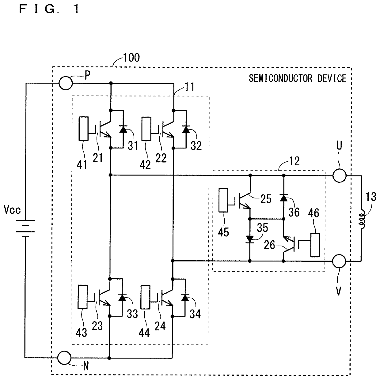
[0034]FIG. 7 is a circuit diagram of a semiconductor device 101 according to Embodiment 1. The semiconductor device 101 is obtained by adding impedance between the anode of each freewheeling diode 31 to 34 of the inverter section 11 and the output terminals or the input terminal in the HERIC circuit 100 of the underlying technique. Specifically, in the upper arm, impedance 51 is connected between the anode of the freewheel diode 31 of the first-phase IGBT 21 and the output terminal U, and impedance 52 is connected between the anode of the freewheel diode 32 of the second-phase IGBT 22 and the output terminal V. And, in the lower arm, impedance 53 is connected between the anode of the freewheel diode 33 of the third-phase IGBT 23 and the input terminal N and impedance 53, 54 is connected between the anode of the freewheel diode 34 of the fourth-phase IGBT 24 and the input terminal N.
[0035]The impedances 51 to 54 are greater than parasitic impedance of the normal ...
embodiment 2
C. Embodiment 2
[0041]
[0042]FIG. 10 is a circuit diagram of a semiconductor device 102 according to Embodiment 2. The semiconductor device 102 is different from the semiconductor device 101 of Embodiment 1 in that the IGBTs 21 to 24 and the freewheel diodes 31 to 34 have different connection paths toward the output terminals U and V or toward the input terminal N.
[0043]Specifically, in the semiconductor device 102, the IGBT 21 is connected to the output terminal U through a path different from that of the freewheel diode 31 connected in antiparallel to the IGBT 21. Also the IGBT 22 is connected to the output terminal V through a path different from that of the freewheel diode 32 connected in antiparallel to the IGBT 22. Also the IGBT 23 is connected to the input terminal N through a path different from that of the freewheel diode 33 connected in antiparallel to the IGBT 23. Also the IGBT 24 is connected to the input terminal N through a path different from that of the freewheel diode...
embodiment 3
D. Embodiment 3
[0053]
[0054]The circuit diagram of the semiconductor device 103 of Embodiment 3 is as illustrated in FIG. 10, and is similar to the semiconductor device 102 of Embodiment 2.
[0055]FIG. 12 illustrates the internal structure of the semiconductor device 103. In the semiconductor device 103, the anodes of the freewheel diodes 31 to 34 of the inverter section 11 are connected to the electrode pattern 63 corresponding to the output terminals U and V or the input terminal N by the external wiring 69. The external wiring 69 constitutes the impedances 51 to 54. In other respects, the semiconductor device 103 is similar to the semiconductor device 102. The external wiring 69 is also referred to as second external wiring.
[0056]
[0057]In the semiconductor device 103 of Embodiment 3, the anodes of the freewheel diodes 31 and 32 are connected to the output terminals U and V, respectively, in the upper arm and the anodes of the freewheel diodes 33 and 34 are connected to the input ter...
PUM
 Abstract
Description
Claims
Application Information
 - R&D
- Intellectual Property
- Life Sciences
- Materials
- Tech Scout
- Unparalleled Data Quality
- Higher Quality Content
- 60% Fewer Hallucinations
Browse by: Latest US Patents, China's latest patents, Technical Efficacy Thesaurus, Application Domain, Technology Topic, Popular Technical Reports.
© 2025 PatSnap. All rights reserved.Legal|Privacy policy|Modern Slavery Act Transparency Statement|Sitemap|About US| Contact US: help@patsnap.com


