
Method for generating vehicle controlling data, vehicle controller, vehicle control system, and learning device for vehicle

Pending Publication Date: 2021-07-15
TOYOTA JIDOSHA KK
View PDF14 Cites 2 Cited by
  • Summary
  • Abstract
  • Description
  • Claims
  • Application Information

AI Technical Summary

Benefits of technology

The patent describes a method for controlling an electronic device in a vehicle based on the vehicle's state and the device's actions. Reinforcement learning is used to update a relationship between the vehicle's state and the device's actions, so that the device can operate in a way that maximizes the expected return. This makes it easier for individuals to control the electronic device in the vehicle and reduces the amount of work needed to set the appropriate relationship between the vehicle's state and the device's actions.

Problems solved by technology

Therefore, one skilled in the art typically needs to perform a large amount of work for adaptation of the filter.

Method used


Image

  • Method for generating vehicle controlling data, vehicle controller, vehicle control system, and learning device for vehicle
  • Method for generating vehicle controlling data, vehicle controller, vehicle control system, and learning device for vehicle
  • Method for generating vehicle controlling data, vehicle controller, vehicle control system, and learning device for vehicle

Examples


first embodiment

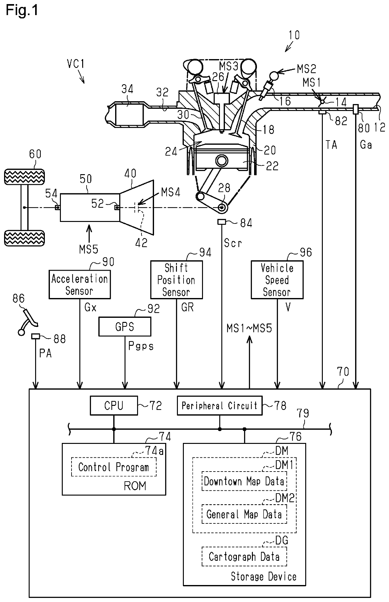
[0035]FIG. 1 is a diagram showing the configurations of a drive system and a controller of a vehicle VC1 in the present embodiment.

[0036]As shown in FIG. 1, an internal combustion engine 10 includes an intake passage 12 provided with a throttle valve 14 and a fuel injection valve 16, which are sequentially arranged from the upstream side. When an intake valve 18 is open, air drawn into the intake passage 12 and fuel injected from the fuel injection valve 16 flow into a combustion chamber 24 defined by a cylinder 20 and a piston 22. In the combustion chamber 24, a mixture of the air and the fuel is burned by spark discharge of an ignition device 26, and energy generated by the combustion is converted into rotational energy of a crankshaft 28 via the piston 22. The burned air-fuel mixture is discharged to an exhaust passage 32 as exhaust when an exhaust valve 30 is open. The exhaust passage 32 is provided with a catalyst 34 used as a post-processing device that purifies the exhaust.

[0...

second embodiment

[0088]A second embodiment will now be described with reference to the drawings. The differences from the first embodiment will mainly be discussed.

[0089]FIG. 7 is a diagram showing a drive system and a controller of a vehicle VC1 in the present embodiment. For the sake of convenience, in FIG. 7, the same reference numerals are given to the components that are the same as those in FIG. 1.

[0090]As shown in FIG. 7, in the present embodiment, the ROM 74 stores a learning program 74b in addition to the control program 74a. The storage device 76 does not store the map data DM and, instead, stores the relationship specifying data DR and torque output mapping data DT. Relationship specifying data DR is data that has been learned in the process shown in FIG. 4. In the relationship specifying data DR, the state s includes the time series data of the accelerator operation amount PA, the vehicle speed V, and the transmission ratio GR, and the action a includes the throttle opening degree instru...

third embodiment

[0094]A third embodiment will now be described with reference to the drawings. The differences from the second embodiment will mainly be discussed.

[0095]In the present embodiment, relationship specifying data DR is updated outside the vehicle VC1.

[0096]FIG. 9 shows the configurations of a control system that executes reinforcement learning in the present embodiment. For the sake of convenience, in FIG. 9, the same reference numerals are given to the components that are the same as those in FIG. 1.

[0097]As shown in FIG. 9, the ROM 74 of the controller 70 arranged in the vehicle VC1 stores the control program 74a but does not store the learning program 74b. The controller 70 includes a communication unit 77. The communication unit 77 is configured to communicate with a data analysis center 130 through an external network 120 of the vehicle VC1.

[0098]The data analysis center 130 analyzes data transmitted from vehicles VC1, VC2, . . . . The data analysis center 130 includes a CPU 132, a...


PUM


Abstract

A method for generating vehicle controlling data includes executing an operating process that operates an electronic device, executing an obtaining process that obtains a state of a vehicle, executing a reward calculation process that assigns a reward based on the state of the vehicle, and an updating process that updates relationship specifying data. The reward calculation process includes a changing process that changes a reward assigned when an area variable equals a second value and a property of the vehicle is a predetermined property from a reward assigned when the area variable equals a first value and the property of the vehicle is the predetermined property.

Description

BACKGROUND1. Field[0001]The following description relates to a method for generating vehicle controlling data, a vehicle controller, a vehicle control system, and a learning device for a vehicle.2. Description of Related Art[0002]Japanese Laid-Open Patent Publication No. 2016-6327 describes an example of a controller that operates a throttle valve, which is an operating unit of an internal combustion engine mounted on a vehicle, based on a value obtained by processing an operation amount of an accelerator pedal through a filter.[0003]The filter needs to set an appropriate operation amount of the throttle valve of the internal combustion engine mounted on the vehicle in accordance with the operation amount (depression) of the accelerator pedal. Therefore, one skilled in the art typically needs to perform a large amount of work for adaptation of the filter. Typically, one skilled in the art performs a large amount of work for adaptation of, for example, an operating amount of an elect...

Claims


Application Information

Patent Timeline
IPC IPC(8): B60W50/00G07C5/02G06N20/00
CPCB60W50/00G07C5/02F02D41/2438B60W2050/0083B60W2520/10G06N20/00B60R16/0231F02D41/2448F02D2200/501G07C5/0808B60W30/182B60W2556/10B60W2552/05B60W2556/45B60W2556/50G06N3/006G06N7/01
Inventor HASHIMOTO, YOSUKEKATAYAMA, AKIHIROOSHIRO, YUTASUGIE, KAZUKIOKA, NAOYA
Owner TOYOTA JIDOSHA KK
Learn More