Method for driving electronic device

a technology of electronic devices and driving systems, applied in the direction of photovoltaic monitoring, electric pulse generator circuits, electric pulse generation by energy-accumulating elements, etc., to achieve the effects of preventing performance degradation, suppressing chemical reactions, and preventing accumulation of charges

Pending Publication Date: 2021-07-08
GLOBAL FRONTIER CENT FOR MULTISCALE ENERGY SYST +1
View PDF0 Cites 2 Cited by
  • Summary
  • Abstract
  • Description
  • Claims
  • Application Information

AI Technical Summary

Benefits of technology

[0032]According to the prevent invention, by applying a specific voltage and current during power transfer, under a power transfer condition, or after completion of power transfer, for stabilizing of power supply source, there are provided advantages of preventing accumulation of charge inside the device to suppress a chemical reaction between a light-absorbing layer and moisture and oxygen in the air and preventing performance degradation caused by ion defects and ion migration, thereby increasing a service life, which is beyond a simple principle of extending service life through periodic rests by such a power transfer method.
[0033]Since the method for driving an electronic device of the present invention effectively extracts electrons and holes accumulated inside the device, it is possible to prevent electrons and holes from accumulating inside the device and from shortening the service life of the device.
[0034]Furthermore, the present invention can provide a method for driving an electronic device capable of increasing the service life and securing the long-term stability of electronic devices, such as an organic thin-film transistor (OTFT), an organic light-emitting diode (OLED), an organic sensor, an organic memory device, and so on.
[0035]In particular, as with concentrator photovoltaic (CPV) systems, when the concentrated light of strong intensity is incident on a device to thereby accelerate the generation of electrons and holes inside the device, the method for driving an electronic device of the present invention can effectively improve the performance and service life of the device.

Problems solved by technology

Since power supply sources such as organic / inorganic perovskite solar cells, and the like exhibit service life of several months at most due to their quite low stability, extending the service life of organic / inorganic perovskite solar cells is a challenge that must be resolved for the phase of commercialization that requires a minimum of a unit of a year.

Method used


Image

  • Method for driving electronic device
  • Method for driving electronic device
  • Method for driving electronic device

Examples


Embodiment Construction

[0062]Hereinafter, a method for transferring electric power to and from a solar cell in accordance with an embodiment of the present invention will be described in detail. The accompanying drawings illustrate exemplary forms of the present invention and are only provided to describe the present invention in greater detail, and the scope of the present invention is not limited thereby.

[0063]In addition, the same or equivalent components are assigned the same reference numerals regardless of the drawings and description thereof will not be repeated, and the size and shape of respective components shown may be scaled up or down for the sake of convenience of description.

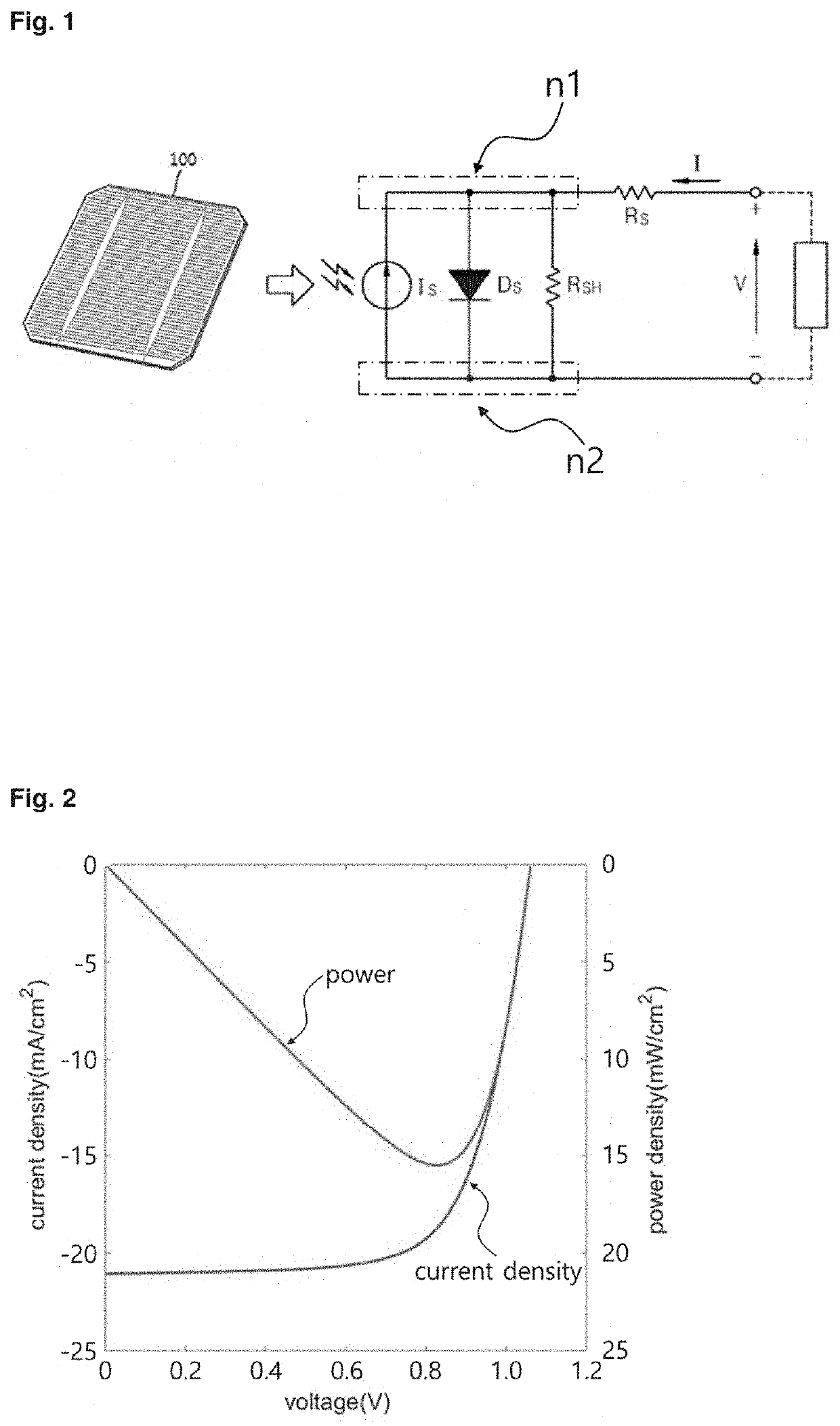
[0064]In the method for driving an electronic device of the present invention, the electronic device may be a solar cell. That is, the method for driving the electronic device of the present invention may be a method for driving a solar cell.

[0065]A method for driving a solar cell in accordance with the present inventio...


PUM

PropertyMeasurementUnit
transfer voltageaaaaaaaaaa
stabilization voltageaaaaaaaaaa
stabilization currentaaaaaaaaaa

Abstract

The present invention provides a method for driving an electronic device so that the electronic device can have higher stability and longer service life. More particularly, proposed is a method for driving an electronic device so that power supply sources including perovskite solar cells, organic solar cells, or the like, or other electronic devices can have higher stability and longer service life.

Description

CROSS REFERENCE TO RELATED APPLICATIONS[0001]This application is a continuation-in-part of copending PCT Application No. PCT / KR2019 / 011478 filed Sep. 5, 2019, entitled “Method For Driving Electronic Device”, which claims the benefits of priority to Korean Patent Application No. KR 10-2018-0106094 filed Sep. 5, 2018, and Korean Patent Application No. KR 10-2019-0109398 filed Sep. 4, 2019, all of which are incorporated herein by reference in their entireties for all purposes.TECHNICAL FIELD[0002]The present invention relates to a method for driving an electronic device, and more particularly, to a method for driving an electronic device so that power supply sources including perovskite solar cells, organic solar cells, or the like, or other electronic devices can have higher stability and longer service life.BACKGROUND[0003]In general, a power transfer method at a maximum efficiency voltage that can be known through the current-voltage characteristics of a solar cell is called maximum...

Claims


Application Information

Patent Timeline
Patent Type & Authority Applications(United States)
IPC IPC(8): H02S50/00H02S99/00H03K3/53
CPCH02S50/00H03K3/53H02S99/00H01L31/02021H10K30/15Y02E10/549Y02E10/56
Inventor CHOI, MAN SOOAHN, NAMYOUNGJEONG, KIWAN
Owner GLOBAL FRONTIER CENT FOR MULTISCALE ENERGY SYST
Why Eureka
Try Eureka