Method for creating multiple electrical current pathways on a work piece using laser ablation

a technology of laser ablation and workpiece, which is applied in the direction of liquid/solution decomposition chemical coating, contacting device, coating, etc., can solve the problems of adding significant cost to the final product, reducing the aesthetics of workpieces, so as to eliminate the need for costly secondary operations and reduce the cost of post-treatment. cost and other issues

Pending Publication Date: 2021-07-08
LACKS ENTERPRISES
View PDF7 Cites 1 Cited by
  • Summary
  • Abstract
  • Description
  • Claims
  • Application Information

AI Technical Summary

Benefits of technology

[0034]It is therefore an aspect of the present disclosure to provide a method for plating a work piece with multiple surface finishes. The method eliminates the need for costly secondary operations to finish the work piece since creating the barrier in electrical conductivity and respectively electroplating the first and second segments of the work piece may be done in an inexpensive and simple process.

Problems solved by technology

This practice, while effective, results in multiple operations and multiple sets of tooling which adds significant cost to the final product.
However, when such work pieces, which include one section employing these surface effects and another part without these effects, are both subjected to electroplating, the leveling characteristic of the electroplated layer on these two sections does not create the visual effect of two distinct metal surface finishes as desired.
Also, the pre and post surface treatments are costly and require an additional operation.
Vacuum metallization and chemical vapor deposition techniques are able to achieve a final product that has segments with different finishes, but are very costly and limited from a performance standpoint in many environments because of the thin layer of metal that results from these techniques.
This additional step increases labor costs and creates an “orange peel” look due to the fact that the organic coating is not completely smooth.
Although this method creates the desired effect, it disadvantageously requires an additional painting operation which adds cost to the final product.
However, the entire part is electrolessly deposited with metal material and the metal is not removed, such that a single current pathway remains, and the separate areas resulting from the photoresist are not electrically isolated.

Method used


Image

  • Method for creating multiple electrical current pathways on a work piece using laser ablation
  • Method for creating multiple electrical current pathways on a work piece using laser ablation
  • Method for creating multiple electrical current pathways on a work piece using laser ablation

Examples


Embodiment Construction

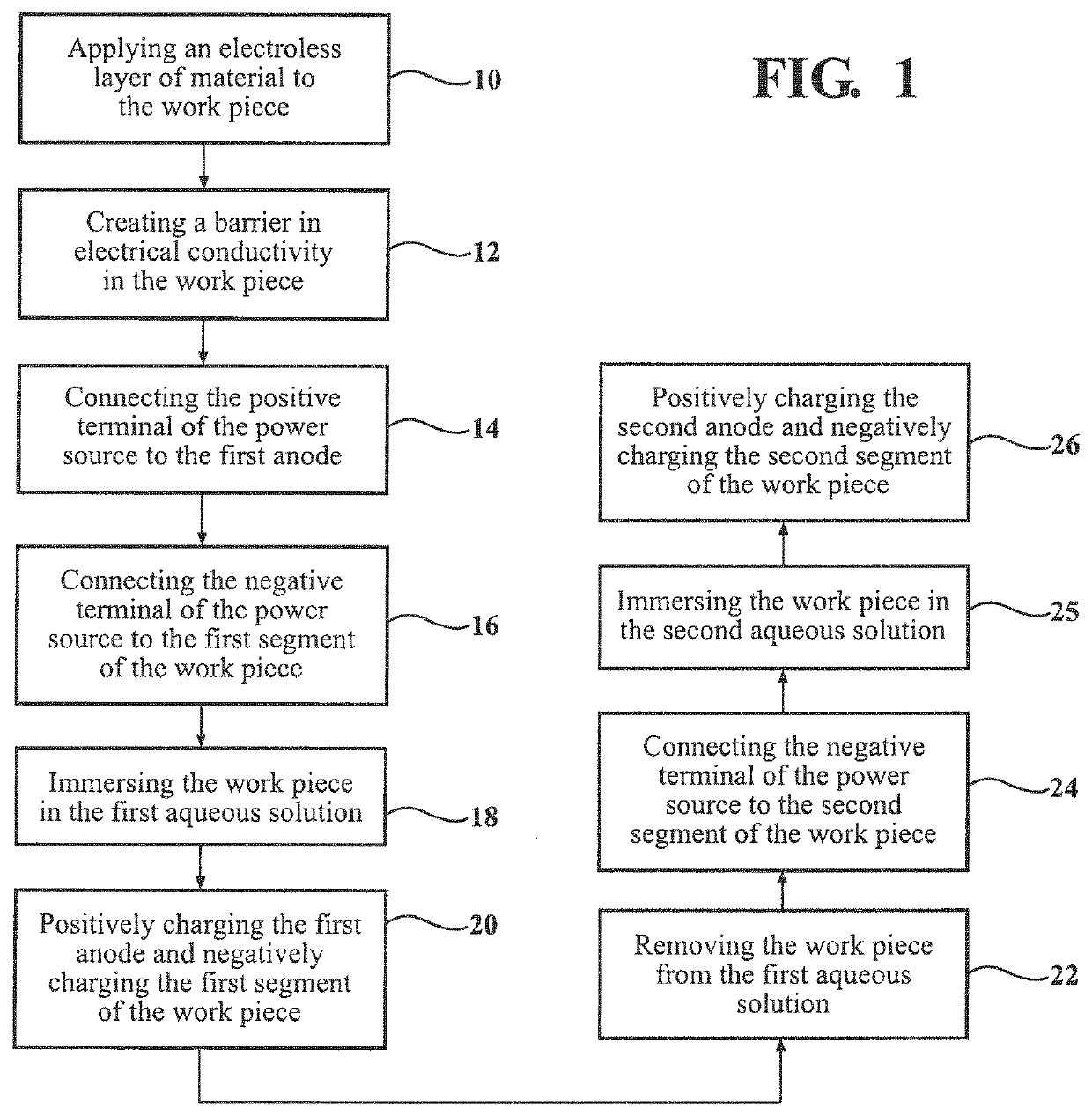
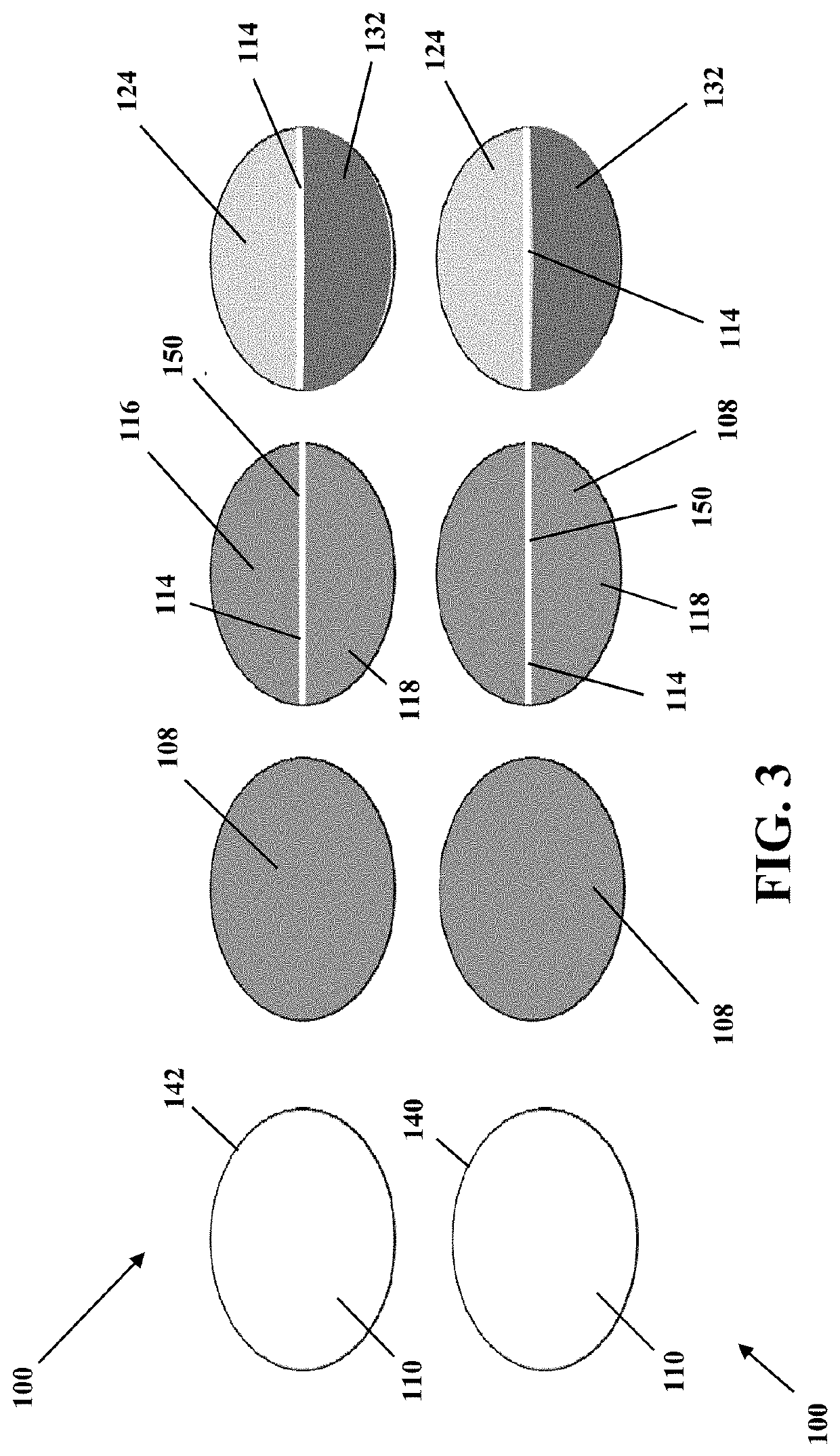
[0043]Referring to the Figures, wherein like numerals indicate corresponding parts throughout the several views, a method is generally shown for plating a work piece 100 using a power source 102 (e.g., a battery) having a positive terminal 104 and a negative terminal 106. It will be appreciated that a variety of suitable power sources may be employed. According to an aspect, the work piece 100 may be configured as a trim component for a vehicle such as a grill, wheel cover or interior trim piece. It will be appreciated that the work piece 100 may be for a variety of different applications, including furniture applications.

[0044]According to an aspect, as exemplarily shown in FIGS. 1-4, the method includes creating a barrier 114 to electrical conductivity in a base substrate layer 110 of the work piece 100. Thereafter, an electroless layer of material 108 can be applied to the base substrate layer 110 of the work piece 100 using an electroless plating process, as generally indicated ...


PUM

PropertyMeasurementUnit
electrical currentaaaaaaaaaa
conductiveaaaaaaaaaa
currentaaaaaaaaaa

Abstract

A method for creating multiple current pathways for plating a work piece is provided. An electroless layer of material is applied to the work piece using an electroless plating process. The method includes creating a barrier in electrical conductivity in the work piece to divide the work piece into a first segment and a second segment which are substantially electrically insulated from one another, prior to electroplating the work piece. After depositing the electroless layer of material, laser ablation is performed on at least a portion of the work piece to remove a portion of the electroless layer of material to define at least a portion of the barrier. Prior to electroless plating, a resist material may be applied to at least a portion of the work piece, with the resist material combining with the removed material to define the barrier.

Description

CROSS-REFERENCE TO RELATED APPLICATIONS[0001]This application is a continuation-in-part of co-pending U.S. patent application Ser. No. 16 / 679,635, filed Nov. 11, 2019, titled “Method for Creating Multiple Electrical Current Pathways on a Work Piece,” which is a continuation-in-part of U.S. patent application Ser. No. 14 / 712,702, filed May 14, 2015, titled “Method for Creating Multiple Electrical Current Pathways on a Work Piece,” the entire content of which is hereby incorporated by reference in its entirety.TECHNICAL FIELD[0002]The present disclosure relates generally to improved aesthetics for work pieces, including by a method of electroplating. More specifically, the present disclosure relates to a method for creating multiple electrical current pathways on a work piece to allow for the presence of multiple separate finishes on a single plastic work piece.BACKGROUND OF THE DISCLOSURE[0003]Plated decorative chrome finishes have long been available for various products in the auto...

Claims


Application Information

Patent Timeline
Patent Type & Authority Applications(United States)
IPC IPC(8): C25D5/02C25D5/56C23F17/00
CPCC25D5/022C23F17/00C25D5/56C23F4/02B44C1/00C23C18/2086C23C18/1653C23C18/1689C25D5/02C25D17/08C25D17/005C25D21/12C25D5/14
Inventor LAVALLEE, MICHAELVAN HOUTEN, GARRY
Owner LACKS ENTERPRISES
Why Eureka
Try Eureka