
Immersive display system for eye therapies

a technology of eye therapy and display system, applied in the field of viewing technology, can solve the problems of poor adaptability to small operating room, considerable eye fatigue, and inability to use 3d screen technology,

Active Publication Date: 2021-07-08
TEC MED S R L TECH MEDICHE
View PDF0 Cites 0 Cited by
  • Summary
  • Abstract
  • Description
  • Claims
  • Application Information

AI Technical Summary

Benefits of technology

The present invention is a hardware-software integrated system that solves the problems of eye fatigue for surgeons during operations. It ensures that the images used in the operation are of optimal quality and immersive for the observer, without the possibility of being distracted. In addition, some surgery operations can be executed without using coaxial light, thereby canceling out the side effects for the patient due to an excessive and prolonged exposure to light.

Problems solved by technology

For the grounds just set forth above, 3D screen technology does not help the surgeon who, in order to make more realistic use of the images, is obliged to make continuous adjustments of the glasses and suffers considerable eye fatigue.
The bulk of the screens is also to be considered: usually 50 inches, which is poorly adaptable to small operating rooms.
A further problem regarding eye operations this time regards the patient.
The ophthalmic microscopes currently available on the market are in fact provided with a light that can have a phototoxic effect and lead to maculopathies.
The prolonged exposure of the eye to such light sources and the possible use of intraocular optical fibers can even lead to irreversible damage.

Method used


Image

  • Immersive display system for eye therapies

Examples


Embodiment Construction

[0010]According to the present invention, a hardware-software integrated system is attained which effectively resolves the abovementioned problems.

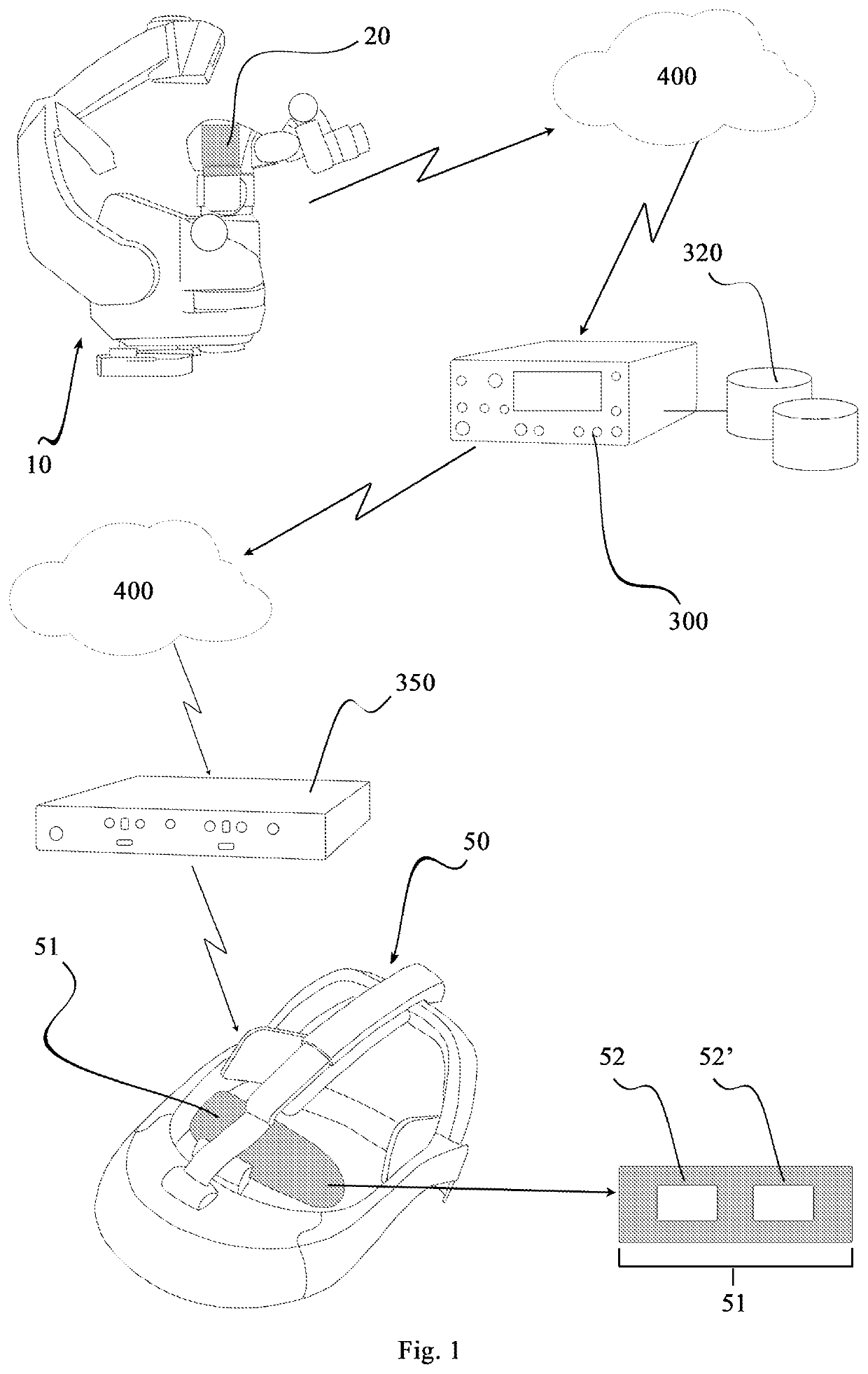
[0011]In addition to the conventional ophthalmic microscope whose use is already widely known in the ophthalmological field, the present system comprises at least:[0012]a double video camera;[0013]a computerized control unit;[0014]a helmet with viewer for virtual reality;[0015]a computerized controller;[0016]a local network infrastructure.

[0017]Said double video camera is advantageously installed on the ophthalmic microscope so as to film the scene of the surgery operation in a continuous manner Due to the connection to the local network, by means of any one wired or wireless technology, the images are transmitted in real time to said computerized control unit. By using a virtual reality software, the images are processed and transmitted, due to a wired or wireless network infrastructure, in real time, to said computerized controller whic...


PUM


Abstract

An immersive display system for eye therapies includes an ophthalmic microscope and: a double video camera, connected to a local network infrastructure; the double video camera oriented for filming the surgery operation; at least one computerized control unit, connected to the local network infrastructure, receiving images from the double video camera and processing them in a three-dimensional digital format; and at least one computerized controller, receiving the images processed by the computerized control unit. Also included is at least one helmet adapted to be worn on the head by the surgeon during the surgery operation, the helmet provided with a viewer arranged before the wearer's eyes, configured for three-dimensional image display, providing virtual reality content; the viewer allows the surgeon exclusive viewing of the three-dimensional images processed by the computerized control unit; the helmet being connected to the local network infrastructure to allow image reproduction in real time.

Description

FIELD OF THE ART[0001]The present invention operates in the field of viewing technologies in a manner known with the name “virtual reality”. More in detail, the object of this patent application is a virtual reality viewing system applied to eye surgery.Prior Art[0002]Conventionally, in eye surgery, ophthalmic microscopes are used which allow the surgeon to have a detailed view of the eye during operation. The most modern models of such microscopes are provided with a monitor, also large-size and very-high definition, on which the images filmed by the microscope are reported in real time.[0003]This implementation of the microscopes is aimed to allow the surgeon to operate while examining the monitor and hence with his / her head up, contrary to what was necessary with the old microscopes, which obliged him / her to be in a curved position and to suffer vision fatigue.[0004]Microscopes provided with 3D screen are also present on the market, which are associated with suitable polarized gl...

Claims


Application Information

Patent Timeline
IPC IPC(8): A61F9/007A61B3/00A61B3/14A61B3/13A61B90/00H04N13/344
CPCA61F9/007A61B3/0058A61B3/145A61B2090/365A61B90/361H04N13/344A61B2090/367A61B3/132A61B90/20
Inventor PUGLISI, LUCA
Owner TEC MED S R L TECH MEDICHE
Learn More