
Grinder

a technology of grinding machine and grinding blade, which is applied in the field of grinding machine, can solve the problems of affecting the quality of grinding machine, and affecting the production efficiency of grinding machine,

Inactive Publication Date: 2021-07-08
SAMSON BRIGHT IND
View PDF0 Cites 3 Cited by
  • Summary
  • Abstract
  • Description
  • Claims
  • Application Information

AI Technical Summary

Benefits of technology

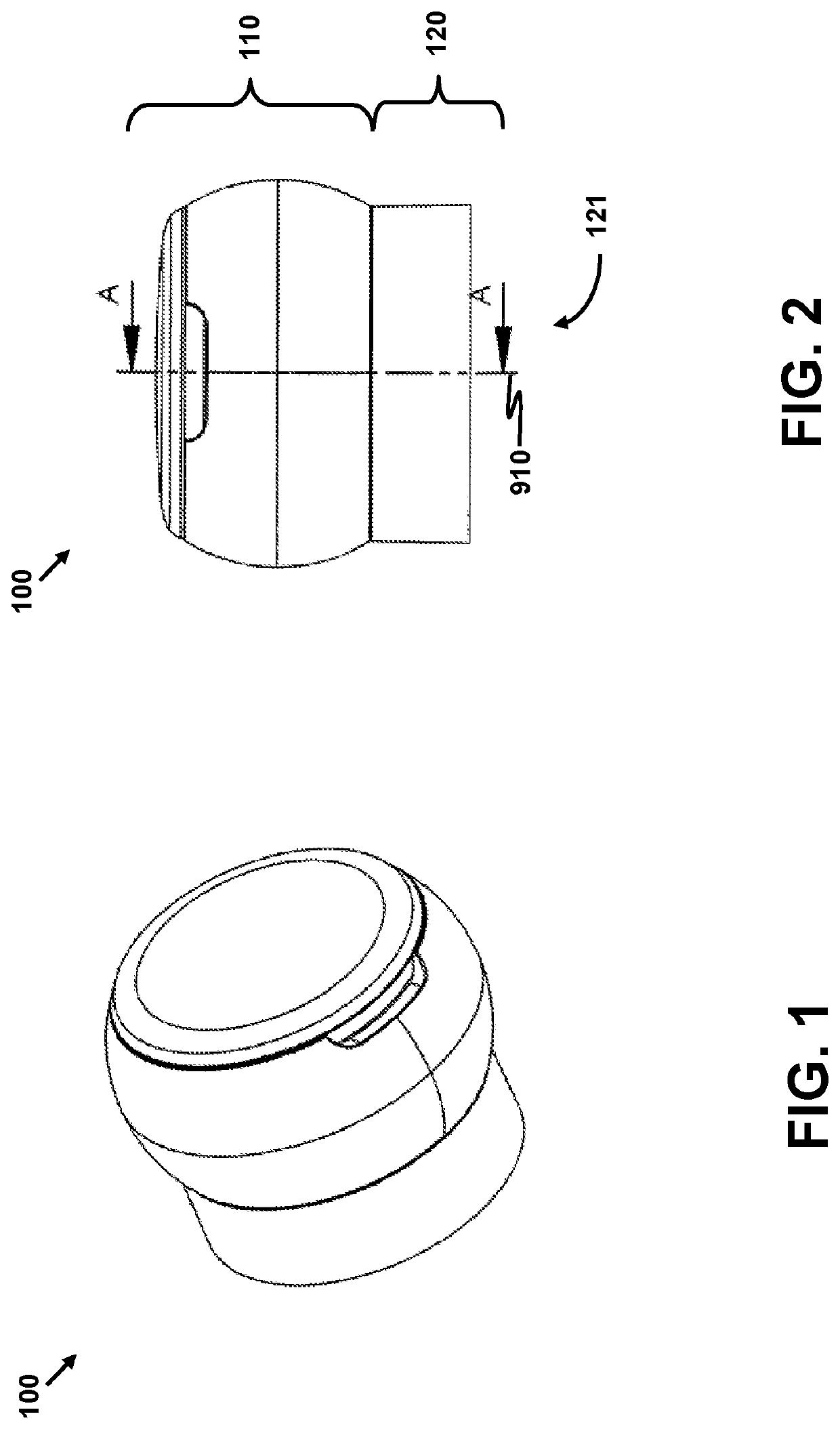
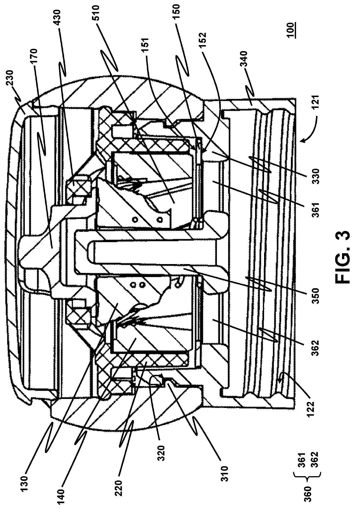
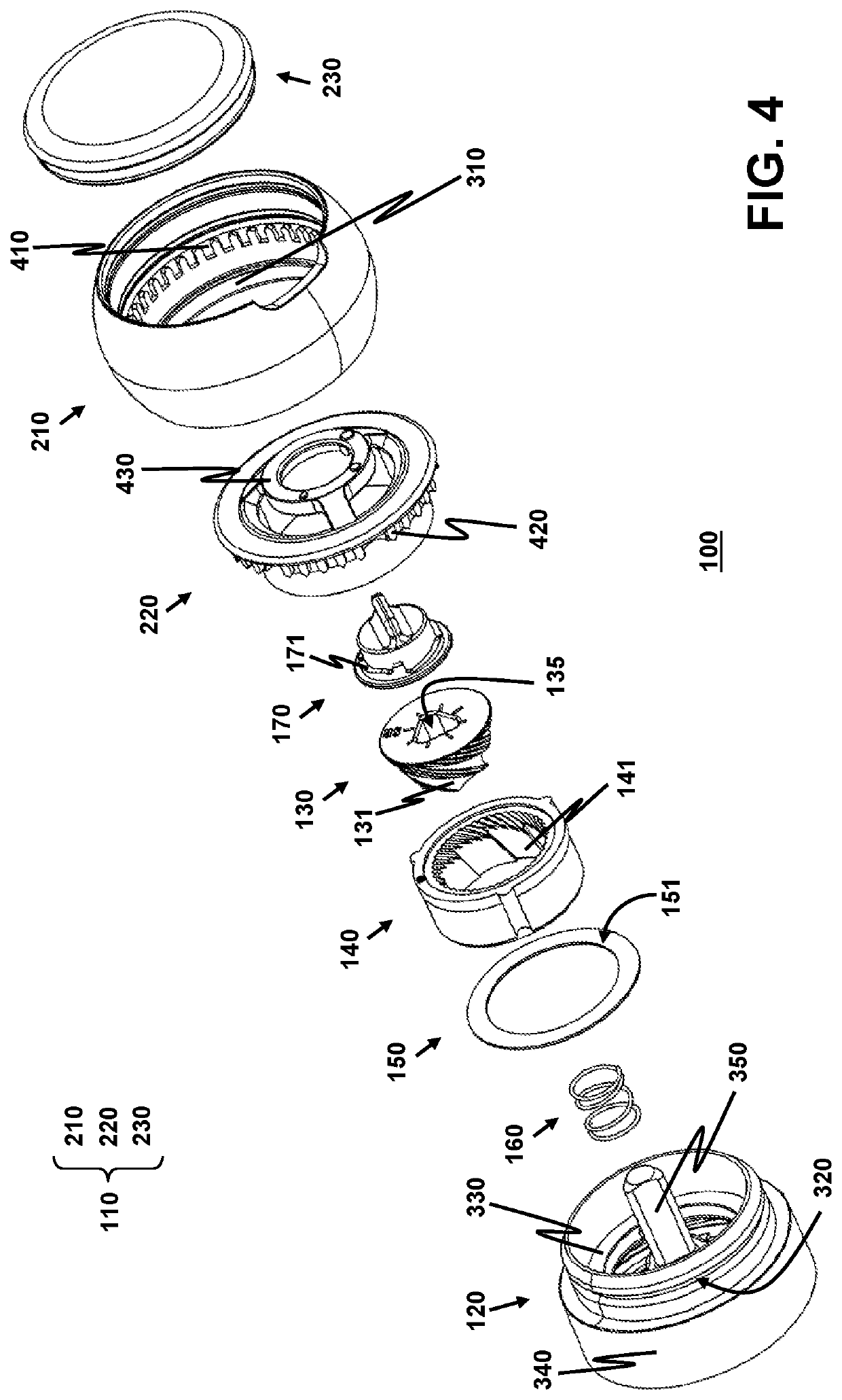
The present invention is a grinder that can make fine solids without wearing down or collecting debris. It has two parts that work together to grind the solids, and a ring-shaped plate that helps keep it all in place. This grinder can be used for grinding both edible and non-edible things. Its design reduces the likelihood of wear and tear on the grinding parts.

Problems solved by technology

A grinder is usually subject to heavy wear because a grinding burr in the grinder is usually in contact with other components of the grinder such that the grinding burr and the other components are abraded by each other during grinding operation, causing wear debris to fall out.
The undesirable generation of wear debris is especially disadvantageous if the grinder is used for grinding edible food such as peppercorns, coffee beans and salt crystals.
However, the cost of manufacturing a grinder that employs a metallic or metal-reinforced burr is substantially increased when compared to using a ceramic burr.
Although the wear debris is health-acceptable, the presence of wear debris in the food obtained after grinding still contaminates the food.
The manufacturing cost of this grinder is generally not low.
Another source of increasing the manufacturing cost is identified in driving the grinding burr.
The shaft is required to have sufficient mechanical strength; otherwise the shaft would be likely to prematurely break down.
A metallic shaft is usually employed in the art, thereby increasing the material cost.

Method used


Image

  • Grinder
  • Grinder
  • Grinder

Examples


Embodiment Construction

[0035]As used herein in the specification and appended claims, the term “avoid” or “avoiding” refers to any method to partially or completely preclude, avert, obviate, forestall, stop, hinder or delay the consequence or phenomenon following the term “avoid” or “avoiding” from happening. The term “avoid” or “avoiding” does not mean that the method is necessarily absolute, but rather effective for providing some degree of avoidance or prevention or amelioration of consequence or phenomenon following the term “avoid” or “avoiding”.

[0036]A first aspect of the present invention is to provide a grinder for grinding solids into fine grains where the grinder has the following advantages. The grinder is configured to avoid wear debris from dropping into the fine grains. Furthermore, the grinder is designed not to include a rigid structure for suspending and precisely positioning any burr inside the grinder in order to keep the manufacturing cost low. The disclosed grinder is particularly use...


PUM


Abstract

A grinder has first and second body parts rotatable to each other. The first and second body parts engage the outer and inner burrs, respectively. A supporting flange in the second body part forms a seat to receive the outer burr. The outer burr is pressed toward the supporting flange to localize the outer burr against undesirable forces generated during grinding. A ring-shaped plate is sandwiched between the supporting flange and the outer burr. The outer burr presses on a bearing surface of the plate. The bearing surface is more resistant to abrasion than the supporting flange, advantageously reducing wear debris generation due to abrasion by the outer burr. Furthermore, a shaft engaging the inner burr is shaped as a triangular column for more effectively transmitting a received torque to the inner burr, allowing a plastic shaft to be used so as to reduce the manufacturing cost.

Description

FIELD OF THE INVENTION[0001]The present invention relates to a grinder.BACKGROUND[0002]A grinder is usually subject to heavy wear because a grinding burr in the grinder is usually in contact with other components of the grinder such that the grinding burr and the other components are abraded by each other during grinding operation, causing wear debris to fall out. The undesirable generation of wear debris is especially disadvantageous if the grinder is used for grinding edible food such as peppercorns, coffee beans and salt crystals.[0003]As disclosed in CN204448154U, U.S. Pat. No. 7,648,094B2, DE202015002785U1, etc., one approach to reduce or even avoid wear debris to be generated from the grinding burr is to use a metallic burr or to coat a metallic layer on the grinding burr. However, the cost of manufacturing a grinder that employs a metallic or metal-reinforced burr is substantially increased when compared to using a ceramic burr. DE102015109726A1 discloses using health-accepta...

Claims


Application Information

Patent Timeline
Patent Type & Authority Applications(United States)
IPC IPC(8): A47J42/08A47J42/10A47J42/34A47J42/38A47J42/04
CPCA47J42/08A47J42/10A47J42/04A47J42/38A47J42/34B02C19/0056B02C23/00
Inventor TANG, YU WING
Owner SAMSON BRIGHT IND
Learn More