
Low Profile Dual-Band Quadrifilar Antenna

a quadrifilar antenna, low-profile technology, applied in the direction of resonant antennas, non-resonant long antennas, substantially flat resonant elements, etc., can solve the problems of poor gain-to-noise-temperature (g/t), position errors, and increased costs

Active Publication Date: 2021-07-01
ATLANTA RFTECH LLC
View PDF0 Cites 3 Cited by
  • Summary
  • Abstract
  • Description
  • Claims
  • Application Information

AI Technical Summary

Benefits of technology

The invention aims to improve the efficiency of antennas by reducing the use of expensive substrate materials. Additionally, the invention addresses the issue of surface waves on the antennas by designing four slots on the top layer to cut unwanted current flow. The invention also offers a natural grounding point for feed lines, making it a platform for a multiple stacked antenna configuration. Finally, the invention mitigates bandwidth limiting heavy relative dielectric by using a lower QHA design, which improves the performance of the antennas.

Problems solved by technology

The design challenge is that the overall band from 1164-1610 MHz has a 32% Bandwidth.
Patch antenna or microstrip antenna are cost and size efficient for use in the High band but typically require thick / heavy dielectric substrate when configured for the Low band, which increases costs and may limit bandwidth.
Phase center variation will result in positional errors.
For multi-feeding point, the main drawback is that the feeding network loss will increase, resulting in poor gain-to-noise-temperature (G / T).
However, these have poor performance due to interaction between the QHA.

Method used


Image

  • Low Profile Dual-Band Quadrifilar Antenna
  • Low Profile Dual-Band Quadrifilar Antenna
  • Low Profile Dual-Band Quadrifilar Antenna

Examples


Embodiment Construction

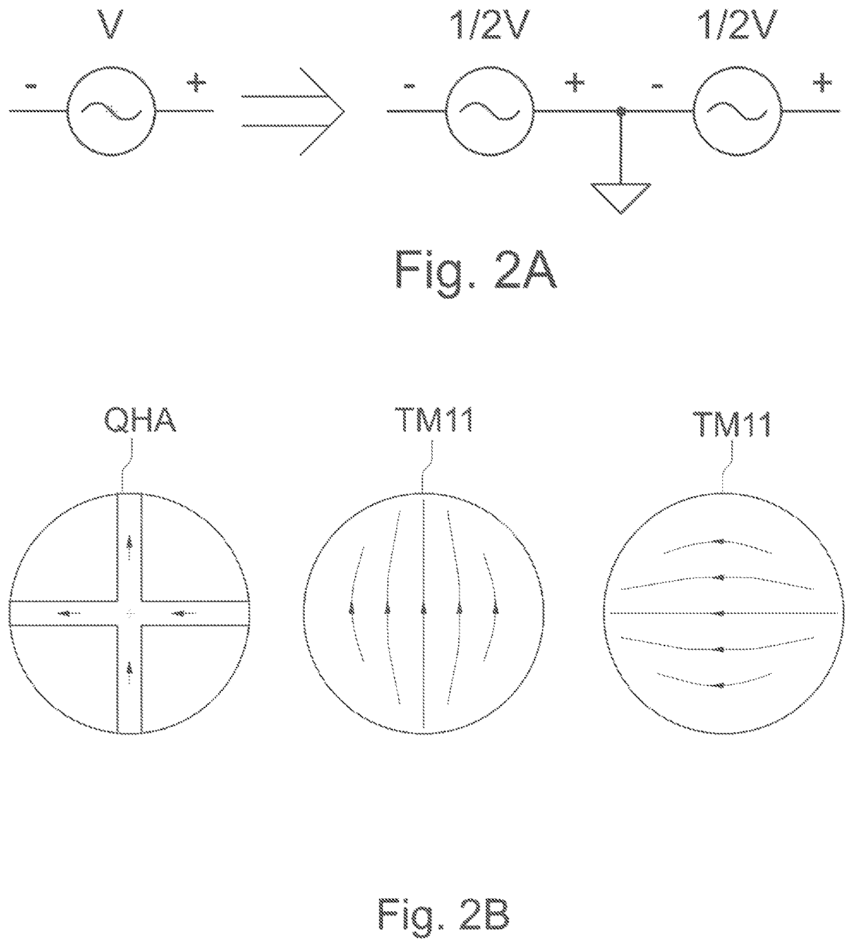
[0042]Referring to FIG. 2A, the original ½ wavelength Kilgus QHA is fed by 2 balun perpendicularly. Once a ground is used, the source can be decomposed to an unbalanced source. FIG. 2B shows the RF current flow of the original ½ wavelength Kilgus QHA and the current of the orthogonal TM11 mode of a circular MSA.

[0043]The inventor has recognized that where a % wavelength Kilgus QHA configuration is applied, the RF current flow and voltage is null at the centers of the filar. Therefore, one can fill this area with conductor without changing the working principle. Further, the MSA TM11 mode equivalent circuit is parallel to that in the QHAs.

[0044]One skilled in the art appreciates that more current path will be excited when the patch size is resonant to a certain frequency. In this case, the lower band will have the half-wave shorted QHA. This is because the feeding impedance near edge reaches the highest point so MSA TM11 mode is mismatched. In other words, the lower band has minimal ...


PUM


Abstract

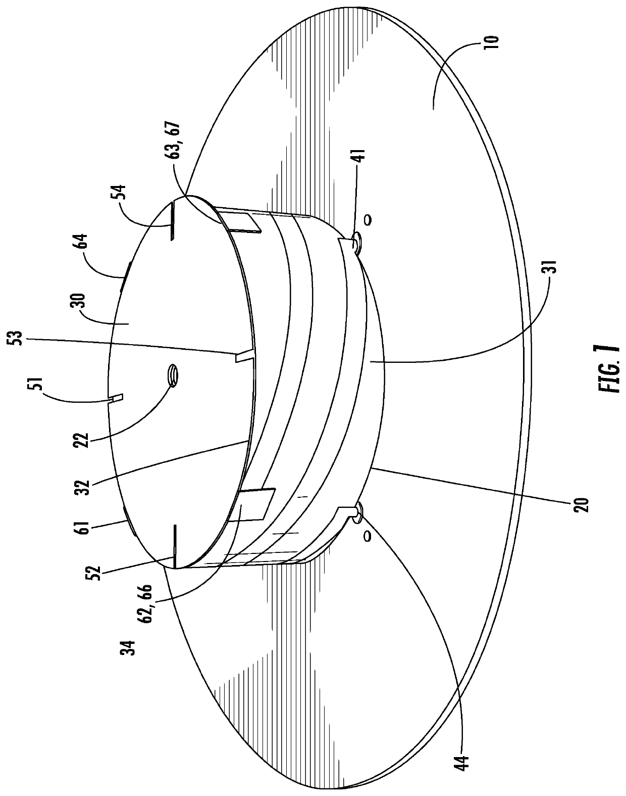
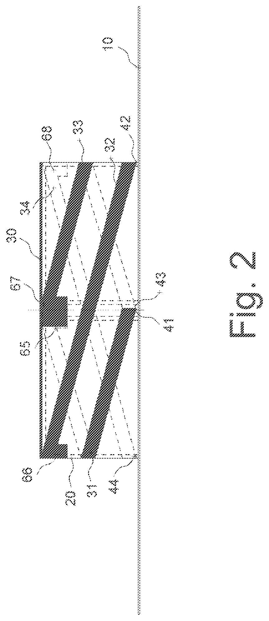
A hybrid antenna structure with a ground plane; a supporting body coupled to the ground plane. The supporting body provided with four helical filar extending from the ground plane, ends of each of the filar coupled at a connection point to a periphery of a patch. The filar each having a length of approximately ½ wavelength of a desired operating frequency. Further, the hybrid antenna structure may be configured for self-diplexing by adding a high-band patch upon the patch, spaced apart by a dielectric spacer.

Description

FIELD OF THE INVENTION[0001]The present invention relates to a low profile dual-band antenna, and more particularly to a low profile helical quadrifilar antenna utilizing a ground plane and a patch that is coupled between each of the filar ends.BACKGROUND[0002]Global navigation satellite systems (GNSS), location and / or elevation indication systems originally designed for the military, are now used worldwide also by both industry and the general public. Examples of growing GNSS uses include: automobile and truck navigation, smartphones, autonomous driving, aviation, smart agriculture, asset / package tracking, surveying, construction, sports equipment, workforce management, high speed trains and unmanned aerial vehicles.[0003]As the importance of reliable GNSS availability has increased, there are a growing number of GNSS systems worldwide such as GPS (U.S.), GLONASS (Russia), Galileo (Europe), and Beidou (China).[0004]Global GNSS Signals are right-hand circular polarized operating on ...

Claims


Application Information

Patent Timeline
Patent Type & Authority Applications(United States)
IPC IPC(8): H01Q9/04H01Q1/48H01Q1/36
CPCH01Q9/04H01Q9/0407H01Q1/36H01Q1/48H01Q9/0435H01Q11/08H01Q5/307
Inventor DU, XIN
Owner ATLANTA RFTECH LLC
Learn More