
Hybrid battery system and method

a hybrid battery and battery technology, applied in the direction of electric variable regulation, process and machine control, instruments, etc., can solve the problems of not being able to meet the needs of compact portable high-current systems, not being able to provide high-current density lithium-ion batteries, and requiring rather long periods of time to be charged to full capacity, etc., to achieve the effect of facilitating the selective provision of power and minimizing the period of tim

Active Publication Date: 2021-06-03
FUNDAMENTAL INNOVATION SYST INT LLC
View PDF5 Cites 0 Cited by
  • Summary
  • Abstract
  • Description
  • Claims
  • Application Information

AI Technical Summary

Benefits of technology

The present invention is a power system and method that uses two types of rechargeable cells. One cell has a higher current density, while the other cell has a lower current density. The system uses switches to selectively connect the two cells, so that the system can quickly charge the high-current density cell and then use the charged cell to charge the low-current density cell when disconnected from the charging station. This reduces the time it takes to charge the device and allows for more efficient use of the rechargeable cells.

Problems solved by technology

Li-Ion batteries provide a high current density, but require rather long periods of time to be charged to full capacity.
This low-density characteristic makes SCs unsuitable for use as a primary power source in devices having high-current demands (i.e., smart phones, tablets, laptops, electric vehicles, etc.).
However, these technologies are ill-suited to meet the needs of compact portable high-current systems that require the ability to attain a stored energy level suitable for device / system operation in a short period of time (seconds or a very few minutes).

Method used


Image

  • Hybrid battery system and method
  • Hybrid battery system and method
  • Hybrid battery system and method

Examples


Embodiment Construction

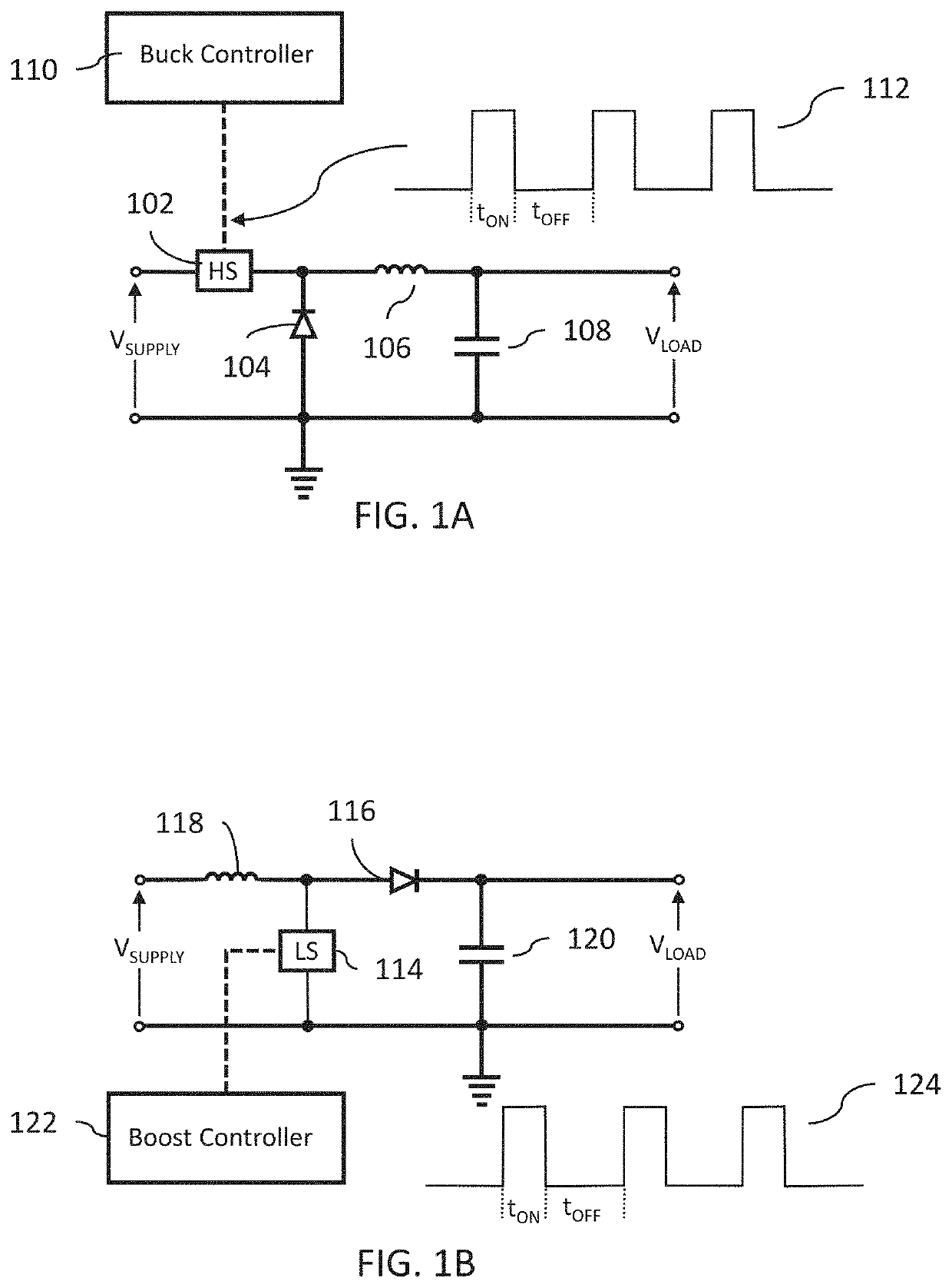
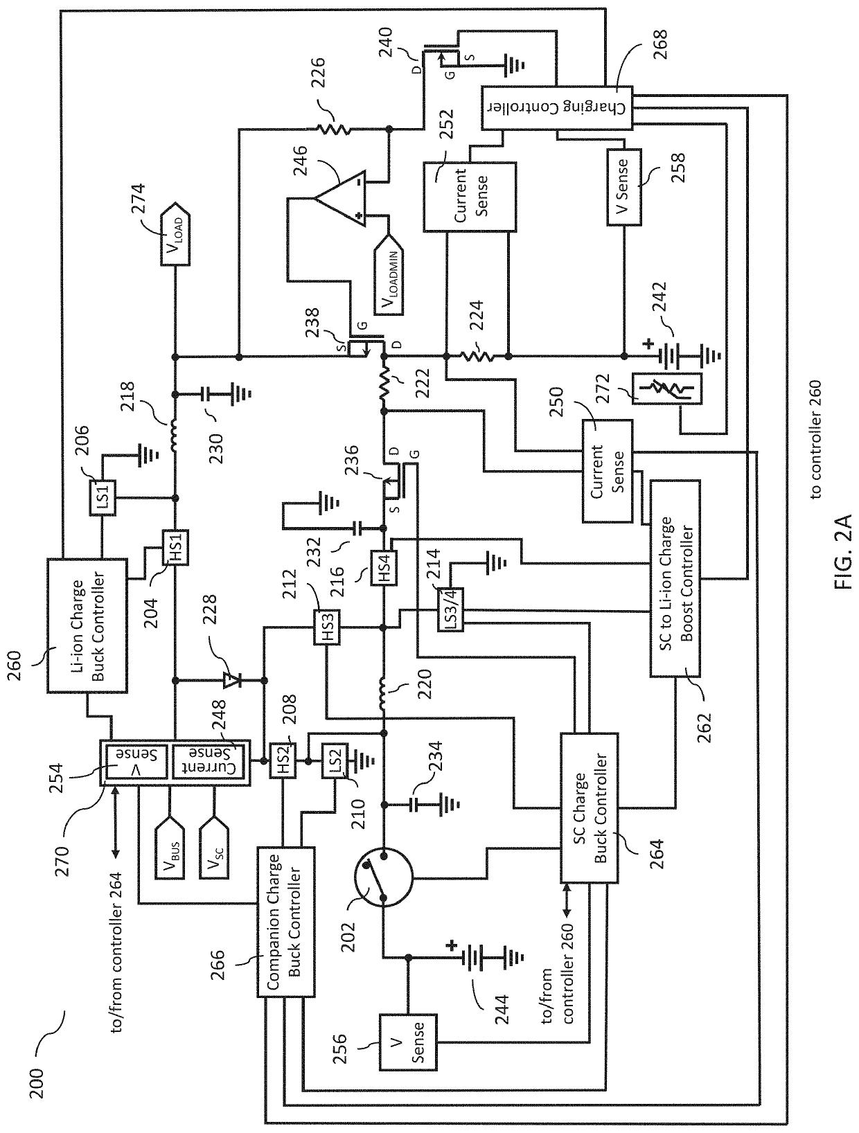
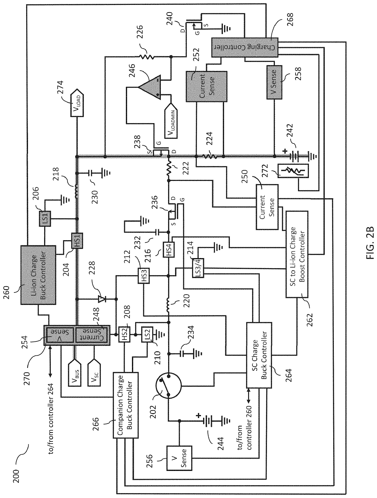
[0018]FIG. 2A is a schematic of a switch-mode power system 200 employing a collection of switches (202, 204, 206, 208, 210, 212, 214, and 216) that are dynamically-actuated so as to selectively interconnect and repurpose a minimal arrangement of components. These components include inductors 218 and 220, resistors 222, 224 and 226, diode 228, capacitors 230, 232 and 234, field effect transistors 236, 238 and 240, lithium-ion (“Li-ion”) battery 242, SC 244, and comparator 246. In addition, the power system also includes current sensors 248, 250 and 252, voltage sensors 254, 256 and 258, controllers 260, 262, 264, 266, 268 and 270, and temperature sensor 272. The controllers are subsystems, controlled by one or more processors or dedicated logic systems, and adapted to manage the charging, discharging and regulation of switch mode power systems. The dynamically-actuated switches are labeled as “high” switches (HSx) or “low” switches (LSx). The low switches are configured to selectivel...


PUM


Abstract

A switching-mode power system and method utilizing a rechargeable primary higher-current density energy cell and a rechargeable secondary lower-current density cell are disclosed. The system and method employ a collection of switches that are dynamically actuated so as to selectively interconnect and repurpose a minimal arrangement of components. This facilitates the selective provision of power to a portable device or system from a rechargeable primary high-current density energy cell or a rechargeable secondary lower-current density cell. In addition, by selectively actuating the switches, the switching-mode power supply is enabled to a) permit the secondary lower-current density cell to quickly attain a charge level suitable for device / system operation when connected to a charging station / power source, b) charge the primary high-current density energy cell, and c) employ the charged secondary lower-current density cell to charge the primary high-current density energy cell when disconnected from the charging station / power source.

Description

CROSS REFERENCE TO RELATED APPLICATION[0001]The present application claims the benefit of the filing date of U.S. Provisional Application No. 62 / 942,955, filed Dec. 3, 2019, the disclosure of which is incorporated by reference.BACKGROUND OF THE INVENTION[0002]The utilization of high current density batteries has increased in recent years to support the rising demand for portable smart devices (phones, tablets, laptop computers, etc.), and electric vehicles (both plug-in and hybrid combustion engine). All of these applications presently rely primarily upon Lithium-Ion (“Li-Ion”) battery technology. Li-Ion batteries provide a high current density, but require rather long periods of time to be charged to full capacity. These typical charging times may range from close to an hour (for batteries charged at 1 C rate) to multiple hours (for larger capacity batteries where 1C charge rate can't easily be accommodated).[0003]Supercapacitors (“SCs”), which are also known as ultracapacitors, of...

Claims


Application Information

Patent Timeline
Patent Type & Authority Applications(United States)
IPC IPC(8): H02J7/00H02M3/158
CPCH02J7/0013H02J2207/20H02M3/158H02J7/007194H02M3/1582
Inventor VESELIC, DUSAN
Owner FUNDAMENTAL INNOVATION SYST INT LLC
Learn More