
Battery housing, battery system and assembly method for a battery system

a battery system and battery technology, applied in the direction of batteries, cell components, electrical equipment, etc., can solve the problems of affecting the operation affecting the safety of the battery system, and the addition of seals, so as to simplify the assembly procedure for the installer and increase the safety of the installer

Pending Publication Date: 2021-06-03
WEBASTO AG
View PDF0 Cites 0 Cited by
  • Summary
  • Abstract
  • Description
  • Claims
  • Application Information

AI Technical Summary

Benefits of technology

The patent proposes a battery housing with a conductor sheath that allows for the connection of battery cells within the housing. This solution offers a more compact construction, reduces the risk of leakages, and provides better protection against misuse or vandalism. The battery housing can also be produced in a modular fashion, providing cost-effectiveness and flexibility in configuration.

Problems solved by technology

However, the provision of additional seals affects the production costs and in particular assembly costs.
This provision of additional seals can also affect the operating safety of the battery system since, to be precise, as the number of seals increases so does the risk of the battery system experiencing leakages.
Due to the high voltages that prevail in a battery system of this type, an installer can be exposed to a safety risk while assembling or dismantling battery systems of this type.

Method used


Image

  • Battery housing, battery system and assembly method for a battery system
  • Battery housing, battery system and assembly method for a battery system
  • Battery housing, battery system and assembly method for a battery system

Examples


first embodiment

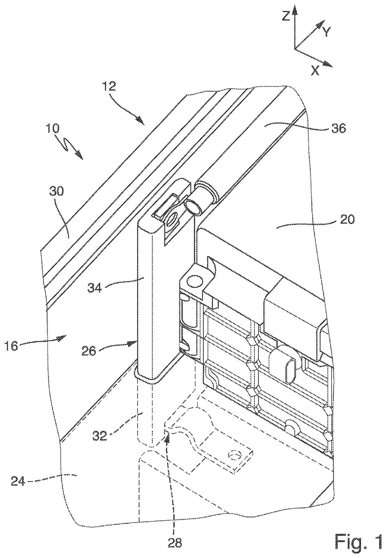
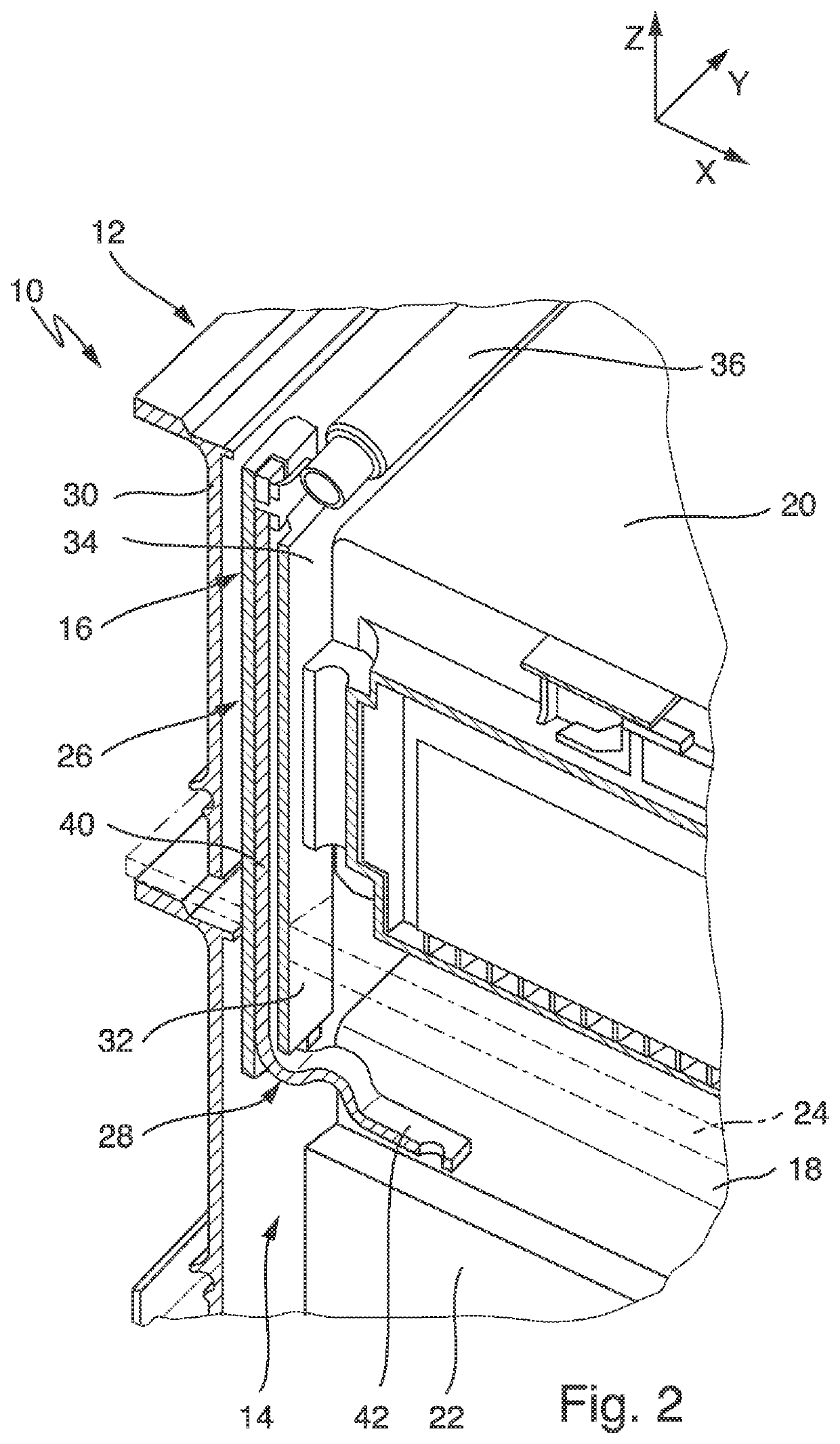
[0060]FIGS. 1 and 2 illustrate schematically a battery system 10 having a battery housing 12 of a The battery system 10 is provided for use in an electric vehicle.

[0061]As illustrated in FIG. 2, the battery housing 12 includes a first receiving chamber 14 and a second receiving chamber 16 that are configured so as to receive multiple battery modules 18, 20 that include in each case a multiplicity of battery cells 22. The first and the second receiving chamber 14, 16 are separated from one another by means of a partition wall 24. In FIGS. 1 and 2, the partition wall 24 is represented as transparent and includes multiple cooling ducts through which a cooling agent can flow so as to cool the battery system.

[0062]FIGS. 1 and 2 illustrate a first battery module 18 that is arranged in the first receiving chamber 14 and a second battery module 20 that is arranged in the second receiving chamber 16. It is also possible to arrange in the first and the second receiving chamber 14, 16 respect...

second embodiment

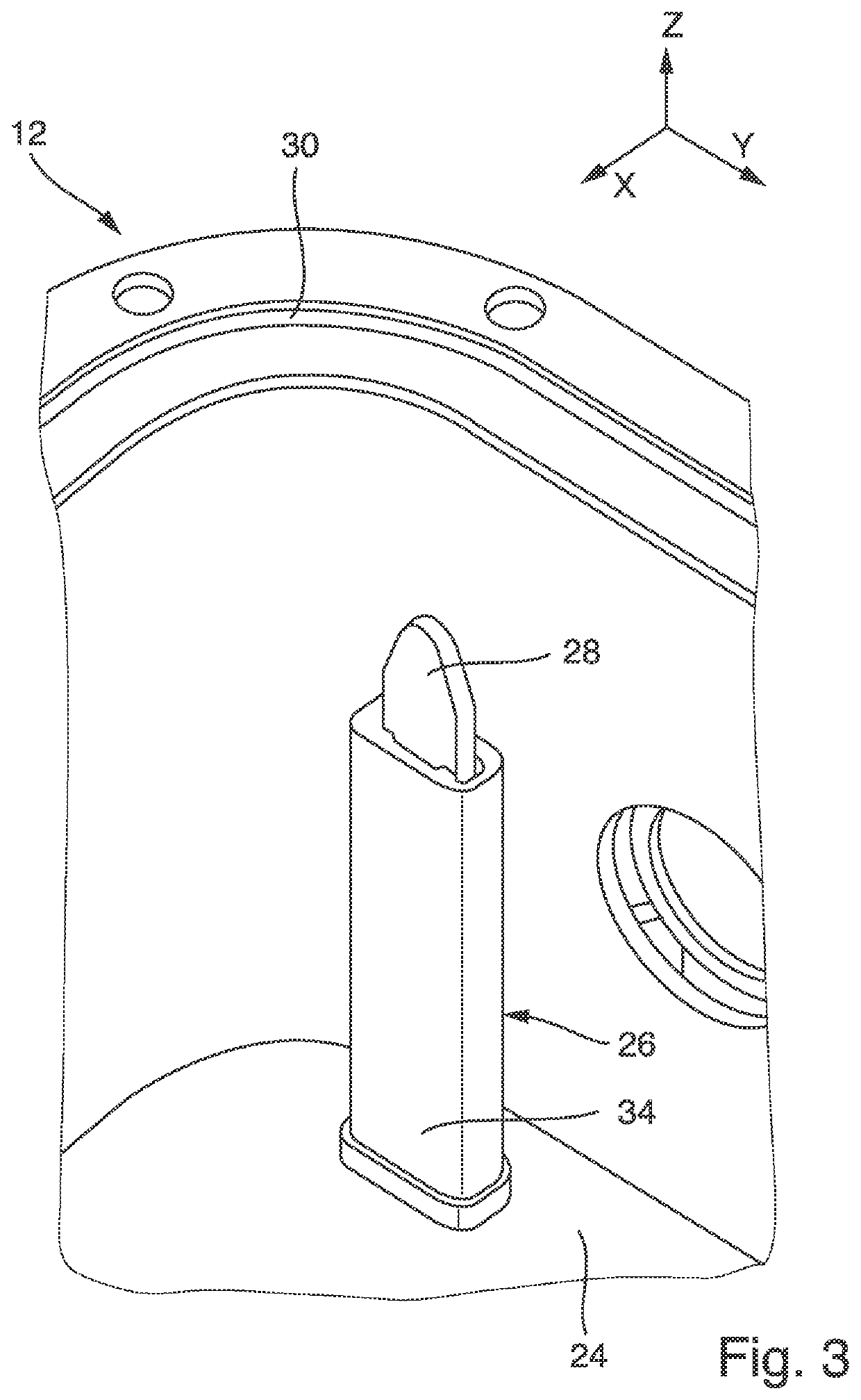
[0073]FIGS. 3 and 4 illustrate a further embodiment of the battery housing 12. In contrast to the configuration illustrated in FIGS. 1 and 2, the second embodiment differs by means of the structure of the conductor sheath 26 and the connecting element 28 that is received therein. In this case, the connecting element 28 protrudes along the extension direction beyond the conductor sheath 26. As illustrated in FIG. 4, the battery housing 12 includes a closure cap 44 that is releasably attached to an end section of the conductor sheath 26. More precisely, the closure cap 44 can include a shape that tapers in the direction of its end. In the state illustrated in FIG. 3, the closure cap 24 is released from the conductor sheath 26.


PUM


Abstract

A battery housing for an electric vehicle includes two receiving chambers, which are separated from one another by means of a partition wall, for receiving battery cells, and a conductor sheath that penetrates the partition wall and can receive an electrical connecting element so as to connect in an electrically conductive manner the battery cells that are to be arranged in a different receiving chamber of the two receiving chambers.

Description

CROSS REFERENCE TO RELATED APPLICATIONS[0001]This application is a national stage of International Application No. PCT / EP2019 / 071138 filed Aug. 6, 2019, which claims priority from German Patent Application 10 2018 119 051.4 filed Aug. 6, 2018 in the German Patent and Trademark Office, the disclosures of which are incorporated herein by reference in their entirety.BACKGROUNDTechnical Area[0002]The present invention relates to a battery housing for constructing a battery system for an electric vehicle. In this case, the battery housing is used to receive a multiplicity of battery cells that can be received for example in battery modules. Moreover, the present invention relates to a battery system for an electric vehicle having a battery housing of this type and an assembly method for a battery system.Related Art[0003]An electric vehicle is understood in this case to be an electrically driven vehicle, in particular a vehicle that is driven purely in an electric manner or a hybrid vehic...

Claims


Application Information

Patent Timeline
IPC IPC(8): H01M50/502H01M50/249H01M50/204H01M50/514H01M50/289H01M50/505H01M50/529
CPCH01M50/502H01M50/249H01M2220/20H01M50/514H01M50/204Y02E60/10H01M50/505H01M50/289
Inventor HAUSSMANN, JOCHEN
Owner WEBASTO AG
Learn More