
Electric compressor

Active Publication Date: 2021-06-03
TOYOTA IND CORP
View PDF6 Cites 0 Cited by
  • Summary
  • Abstract
  • Description
  • Claims
  • Application Information

AI Technical Summary

Benefits of technology

The present invention provides an electric compressor that has two technical effects. The first effect is that it prevents the size of the compressor from increasing. The second effect is that it reduces the noise in the current flow that affects the detection signals of the current sensor, which helps to accurately measure the output current.

Problems solved by technology

This increases a size of the motor controller.
This causes a fear that the detection signals are affected by noise from the switching elements by the extended length of the trace.
In particular, when a trace on the high voltage circuit board crosses the current path formed on the high voltage circuit board, the detection signals are especially affected by the noise to a great extent.

Method used


Image

  • Electric compressor
  • Electric compressor
  • Electric compressor

Examples


Embodiment Construction

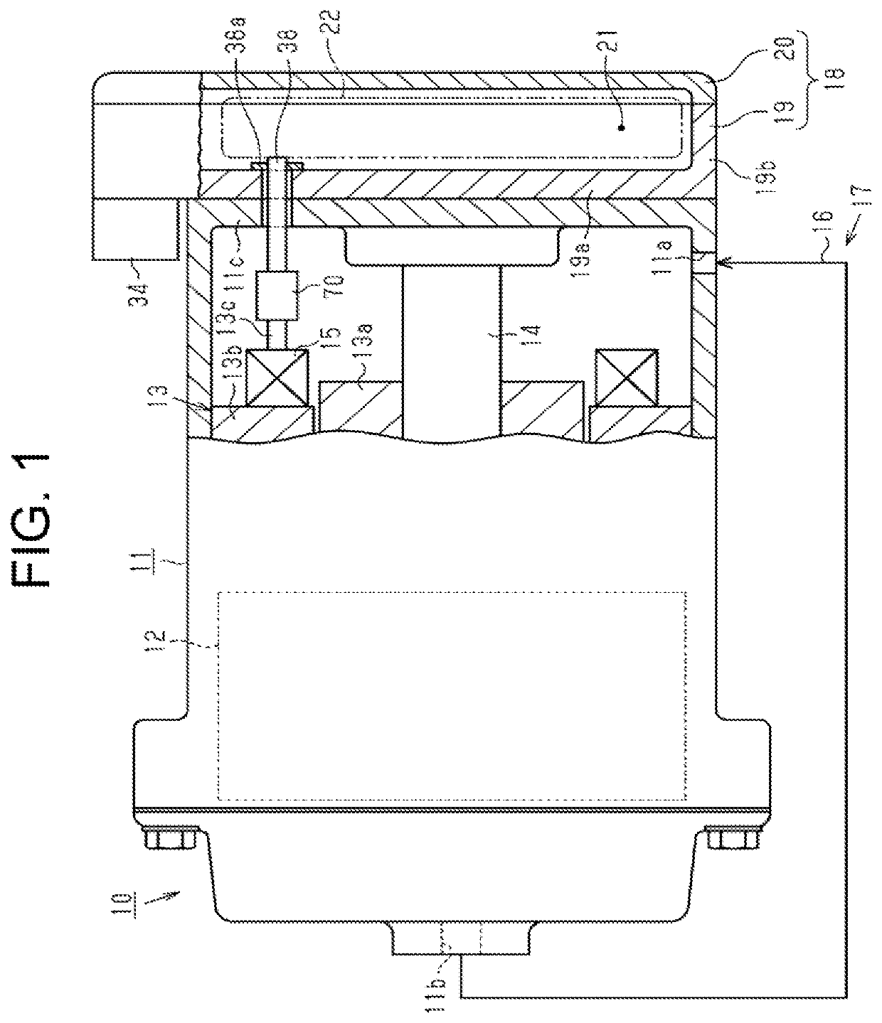
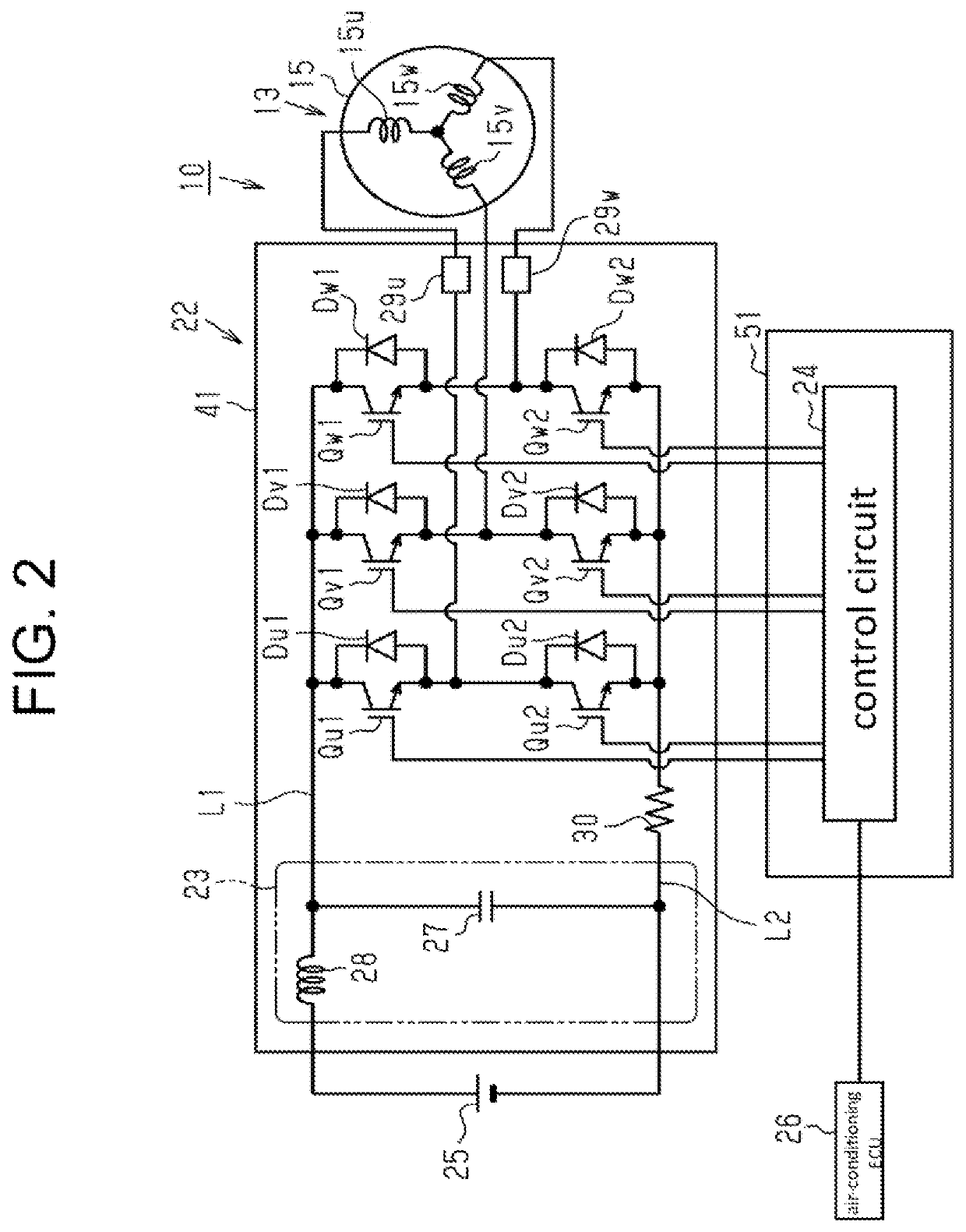
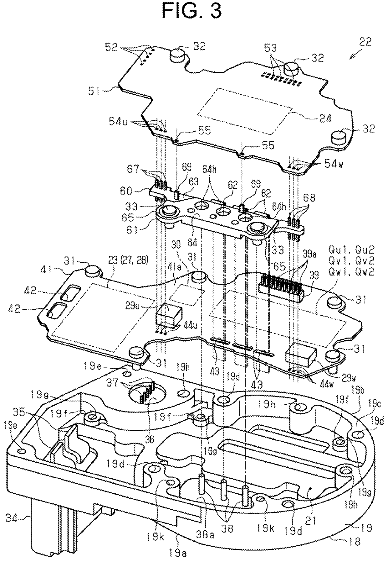
[0017]The following will describe an electric compressor according to an embodiment of the present disclosure with reference to the accompanying drawings from FIG. 1 to FIG. 6. The electric compressor according to the present embodiment is, for example, used for a vehicle air conditioner.

[0018]As illustrated in FIG. 1, an electric compressor 10 includes a housing 11 in which a compression portion 12 configured to compress liquid refrigerant and an electric motor 13 configured to drive the compression portion 12 are accommodated. The compression portion 12 is a scroll type compression portion which includes, for example, a fixed scroll (not shown) fixed in the housing 11 and a movable scroll (not shown) disposed so as to face the fixed scroll.

[0019]An inlet port 11a and an outlet port 11b are formed through the housing 11. In addition, a rotary shaft 14 is accommodated in the housing 11. The rotary shaft 14 is rotatably supported by the housing 11. The electric motor 13 includes a ro...


PUM


Abstract

An electric compressor includes an electric motor, and a motor controller configured to drive the electric motor. The motor controller includes a high voltage circuit board on which switching elements are mounted, a low voltage circuit board on which a control circuit controlling switching operation of the switching elements is mounted, an input connector, an output connector, and a current sensor. The high voltage circuit board and the low voltage circuit board are stacked with each other. The output connector is integrated with a detection busbar that provides electrical connection between the high voltage circuit board and the low voltage circuit board, and through which detection signals indicative of the output current are output to the control circuit.

Description

CROSS-REFERENCE TO RELATED APPLICATION[0001]This application claims priority to Japanese Patent Application No. 2019-215191 filed on Nov. 28, 2019, the entire disclosure of which is incorporated herein by reference.BACKGROUND ART[0002]The present disclosure relates to an electric compressor.[0003]An electric compressor generally includes an electric motor and a motor controller that drives the electric motor. For example, Japanese Patent Application Publication No. 2017-175807 discloses an electric compressor that includes a high voltage circuit board (high heat dissipation circuit board) on which switching elements are mounted and a low voltage circuit board (control circuit board) on which a control circuit for controlling switching operation of the switching elements is mounted. The high voltage circuit board and the low voltage circuit board are stacked with each other.[0004]A motor controller of the electric compressor in the Publication has an input connector that provides ele...

Claims


Application Information

Patent Timeline
IPC IPC(8): F04B35/04F04B39/12F04B39/06H02M7/00H02K5/22H02K11/33
CPCF04B35/04F04B39/121F04B39/06F04B2203/0201H02K5/225H02K11/33H02M7/003F04B49/06G01R19/0092G01R31/343F04C18/0215F04C29/0085F04C2240/808F04C2240/81F04C2270/075F04C2240/803
Inventor OKADA, SATOSHITADA, YOSHIFUMIKINOSHITA, YUSUKE
Owner TOYOTA IND CORP
Learn More