
Method for trimming a bent tube

a technology of bent tubes and cutting methods, which is applied in the field of bent tubes, can solve the problems of difficult cutting of bent tubes in front of behind the tube, low bending radius dimensional accuracy, and high dimensional accuracy of bent tubes, and achieve the effect of reducing labor intensity and reducing labor intensity

Pending Publication Date: 2021-06-03
JENOPTIK AUTOMATISIERUNGSTECHN
View PDF9 Cites 0 Cited by
  • Summary
  • Abstract
  • Description
  • Claims
  • Application Information

AI Technical Summary

Benefits of technology

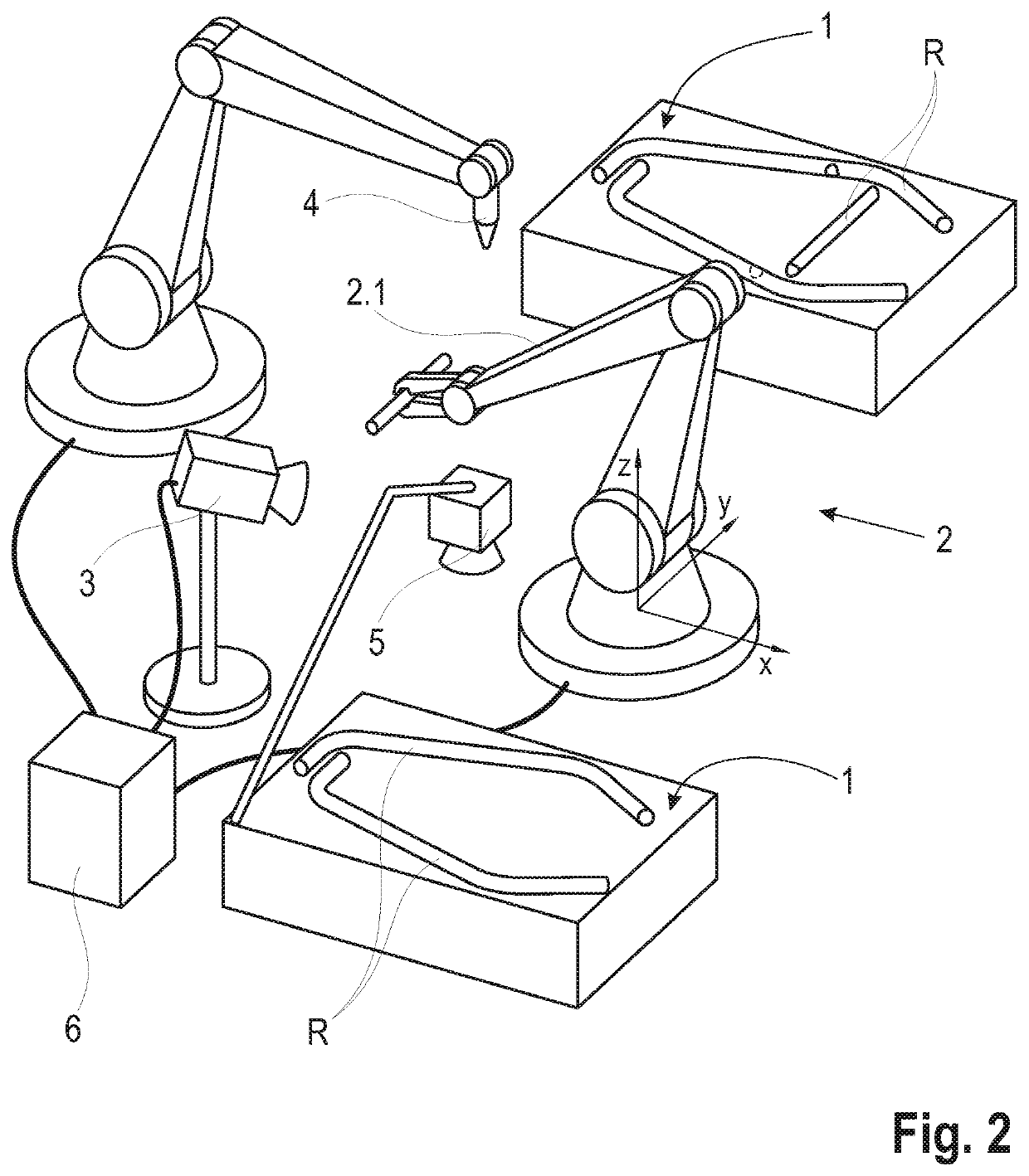
The invention provides a method for trimming a tube that is more automated and allows for precise cutting with minimal tolerance. The position of the tube on a feed surface is recorded, and the desired cutting contour is corrected for the tube. The laser beam is guided along the correction to produce the actual cutting contour. To ensure a higher quality product, the tolerance of the cutting edges is set to be very low, allowing for minimal positional deviation when welding onto another tube.

Problems solved by technology

Bent tubes exhibit high dimensional accuracy as far as their length and cross-section are concerned, but only very low dimensional accuracy in terms of the bending radius resulting from the two- or three-dimensional bending of the tubes.
This makes it difficult to perform cuts on the bent tube in front of and behind the tube bend in such a way that the resulting cutting contours have a reproducible position in relation to each other.
Due to the geometric tolerances of the tubes, a defined automated pick-up by a gripper and fitting via the reference holes in the workpiece receptacle is not possible.
A disadvantage in this case is, on the one hand, that due to the fixed position of the tube in the workpiece receptacle, the tube is accessible for a cutting tool such as a laser beam only to a limited extent.
This leads to an increased expenditure of time and equipment.
On the other hand, out-of-tolerance deviations in the shape of the tube outside the contact area of the receptacle are not detected, which may result in a cutting contour being cut out-of-tolerance on a tube and such a faulty tube being fed for further processing without being identified as faulty.
Especially in the manufacture of complex welded assemblies, such as tubular frames, it is particularly disadvantageous if it is not detected until the later process step of welding the tubes to each other that the tubes cannot be joined together at all interfaces because the cutting contours on individual tubes deviate too far from a specified desired position and the resulting deviations in the spatial position of the tubes relative to each other accumulate within a tolerance chain.

Method used


Image

  • Method for trimming a bent tube
  • Method for trimming a bent tube

Examples


Embodiment Construction

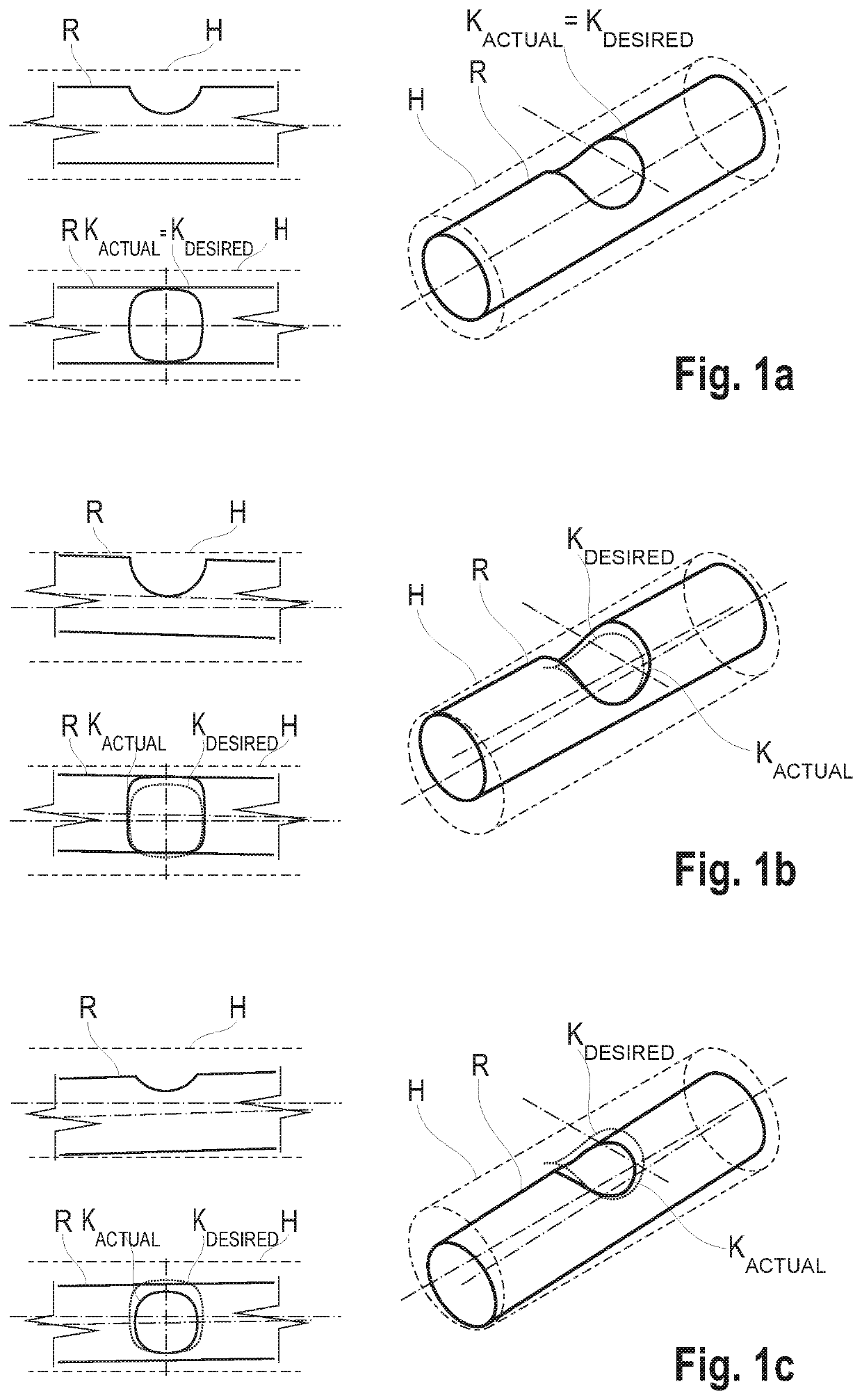
[0027]In a first process step, a tolerance envelope H is calculated for a bent tube R to be trimmed. It envelops the tube R either completely or only partially and is calculated in such a way that the tube R, which can be inserted completely into the tolerance envelope H, lies within a shape tolerance. The tolerance envelope H is stored together with the related desired cutting contours KDESIRED for the tube R. Advantageously, the desired cutting contours KDESIRED lie within the tolerance envelope H such that they coincide with the actual cutting contours KACTUAL along which the tube R is intended to be trimmed, when an ideal tube R lies ideally within the tolerance envelope H. FIG. 1a shows such a situation in a simplified manner, with reference to a straight tube R. The desired cutting contour KDESIRED is advantageously defined such, with respect to the tolerance envelope H, that potential deviations in the position of the actual cutting contours KACTUAL cut on the tubes R lying d...


PUM


Abstract

A method for trimming a bent tube along an actual cutting contour, wherein a virtual tolerance envelope is calculated for the tube and a laser beam cutting the actual cutting contour is guided along a desired cutting contour related to the tolerance envelope, wherein the actual cutting contour is produced as a projection of the desired cutting contour or the laser beam is guided along the corrected desired cutting contour, which then corresponds to the actual cutting contour.

Description

PRIORITY CLAIM[0001]The present application is a National Phase entry of PCT Application No. PCT / DE2018 / 100991, filed Dec. 5, 2018, which claims priority from German Patent Application 10 2017 129 107.5, filed Dec. 7, 2017, the disclosures of which are hereby incorporated by reference herein in their entirety.FIELD OF THE INVENTION[0002]The invention relates to bent tubes. More specifically, the invention relates to methods and systems for advantageously trimming bent tubes.BACKGROUND OF THE INVENTION[0003]Bent tubes exhibit high dimensional accuracy as far as their length and cross-section are concerned, but only very low dimensional accuracy in terms of the bending radius resulting from the two- or three-dimensional bending of the tubes. Variations in bending radius lead to variations in the line of the tube axis. This makes it difficult to perform cuts on the bent tube in front of and behind the tube bend in such a way that the resulting cutting contours have a reproducible posit...

Claims


Application Information

Patent Timeline
IPC IPC(8): B23K26/38
CPCB23K26/38B23K2101/06B23K26/032B23K26/04B23K26/08B23K26/044
Inventor STEINBACH, SEBASTIANSCHELLER, TORSTENREMM, MARKUSREICHL, TORSTENLANGEBACH, JAN
Owner JENOPTIK AUTOMATISIERUNGSTECHN
Learn More