Antenna module
a technology of antenna modules and antenna modules, applied in the direction of antenna details, antennas, basic electric elements, etc., can solve the problems of many technical problems to be overcome, the broadband frequency or radiation efficiency of the antenna unit cannot be effectively improved, and the use of low and medium frequency bands below 6 ghz has become very crowded, so as to improve the radiation efficiency reduce the lateral and backward radiation of the antenna module, and improve the directivity of the antenna module
- Summary
- Abstract
- Description
- Claims
- Application Information
AI Technical Summary
Benefits of technology
Problems solved by technology
Method used
Image
Examples
first embodiment
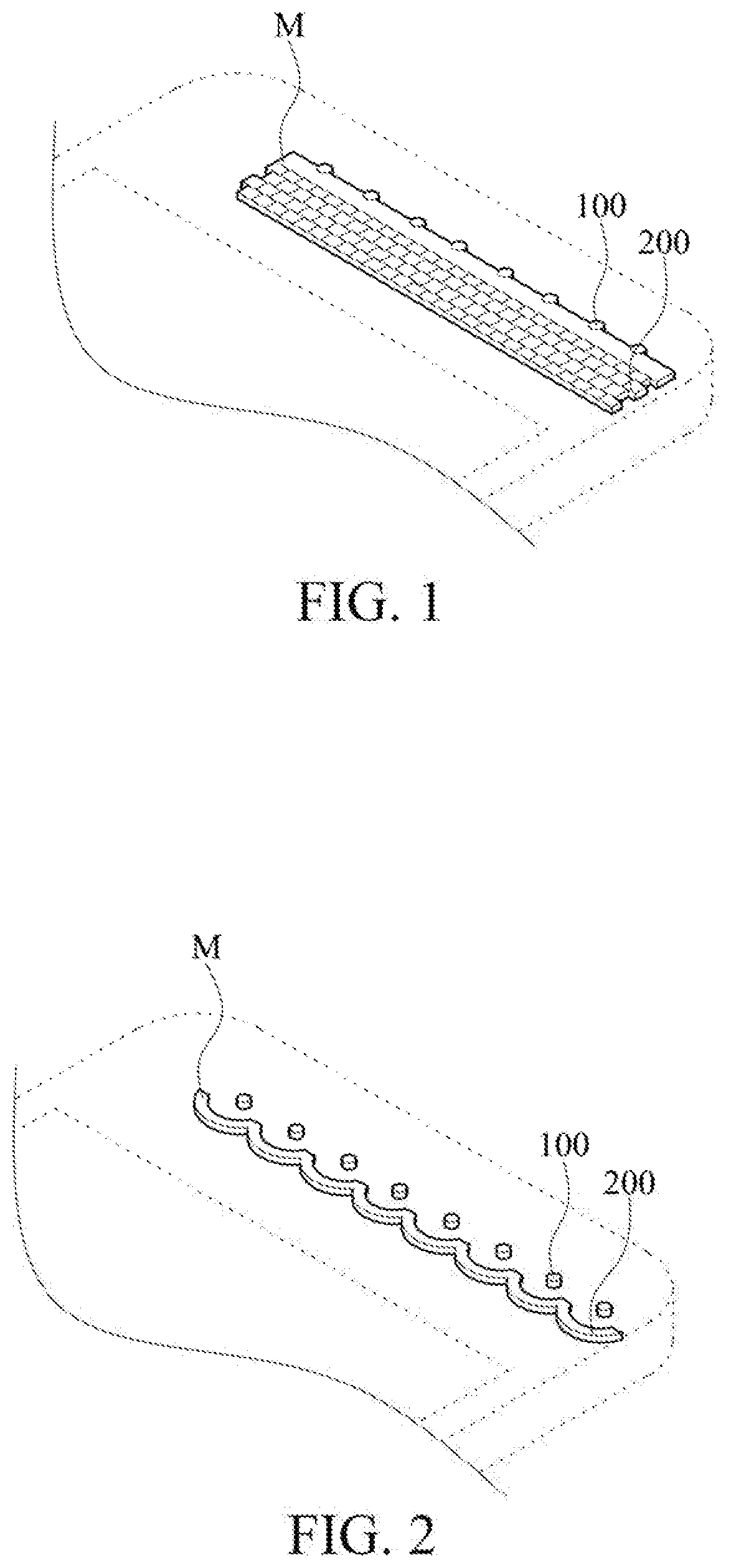
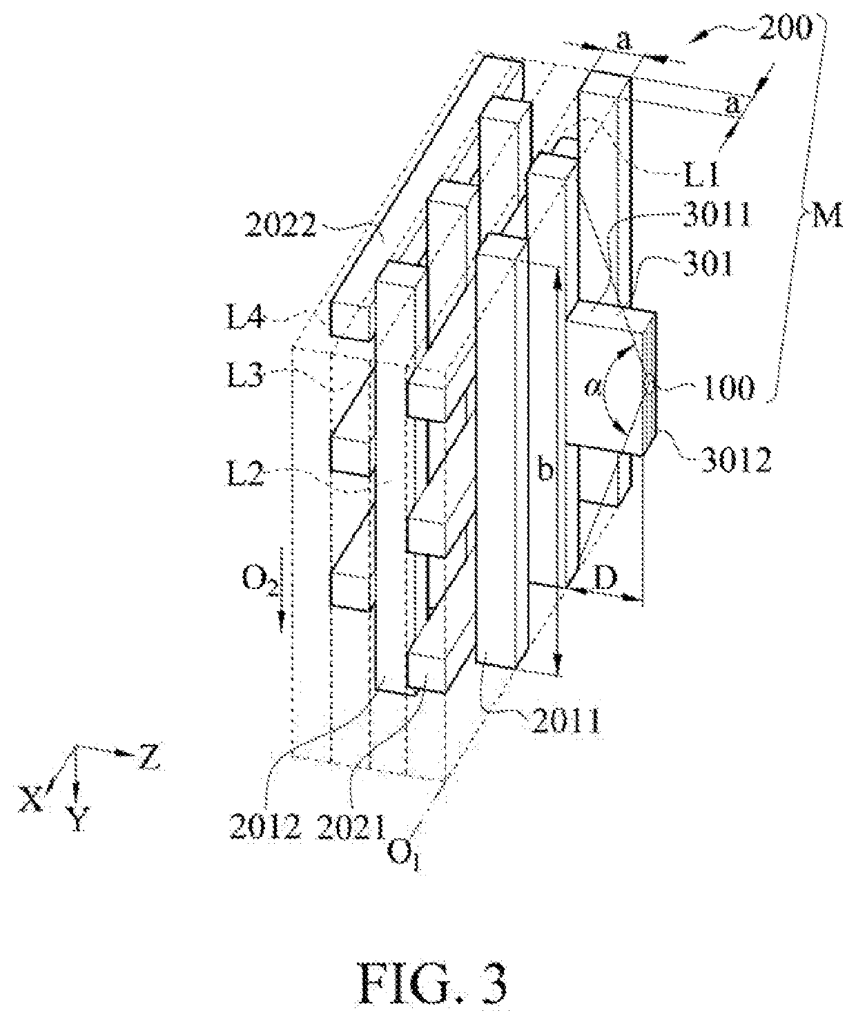
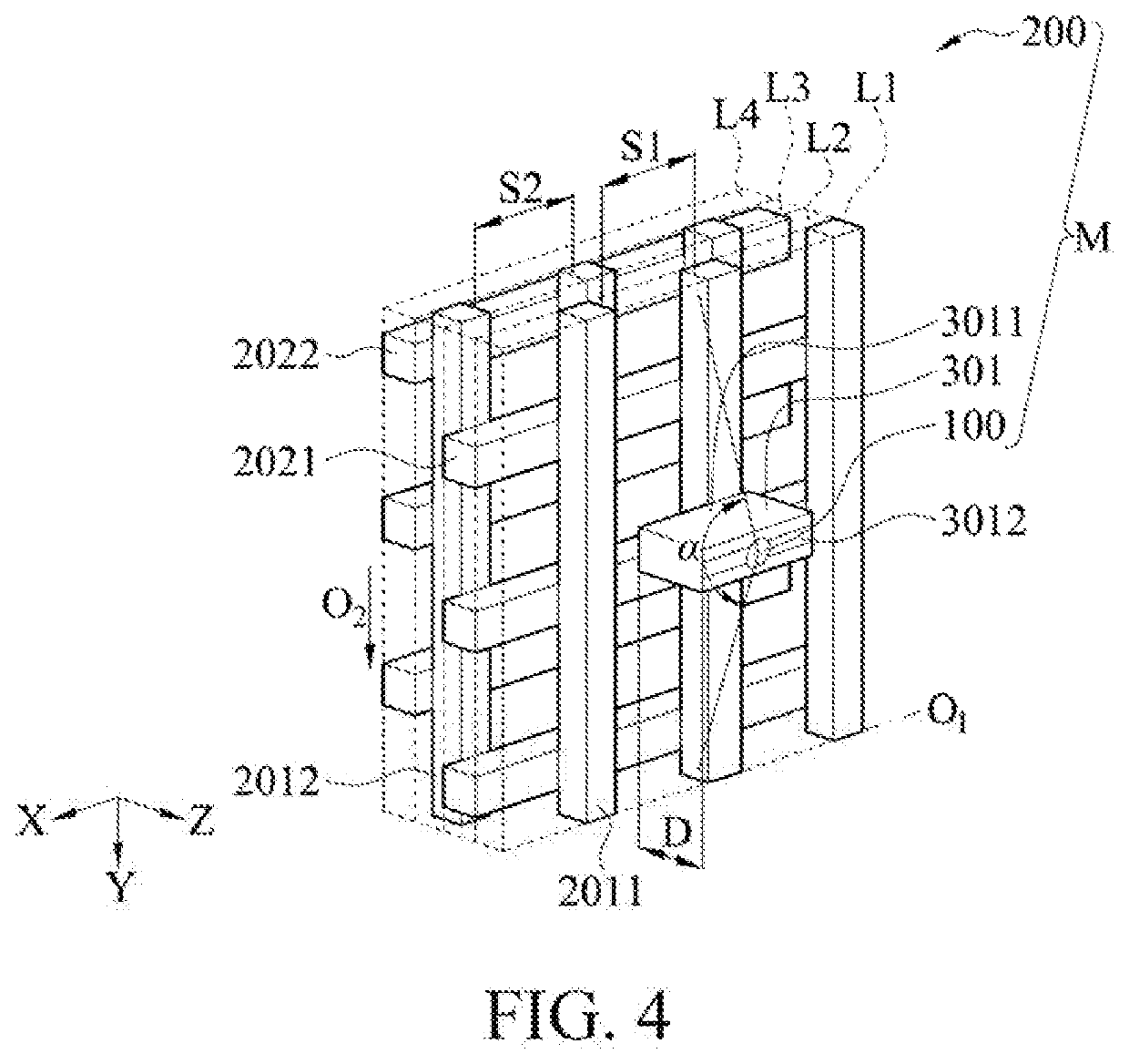
[0042]Please refer to FIG. 3 and FIG. 4 at the same time. FIG. 3 is a schematic perspective view of one implementation pattern of a first embodiment of the instant disclosure. FIG. 4 is a schematic perspective view of one implementation pattern of a first embodiment of the instant disclosure. The antenna module M in the present embodiment includes an antenna 100 and a periodic structure 200. The antenna 100 is configured to transmit or feed a signal. The signal particularly refers to a signal in a millimeter wave band, but the instant disclosure is not limited thereto. A side of the periodic structure 200 facing the antenna 100 forms a return region for returning electromagnetic waves. The antenna 100 and an edge of the periodic structure 200 form an angle α, and the angle is less than 45 degrees.
[0043]The antenna 100 may be coated with a metal wire through a dispenser and a robot arm, or coated on a surface of the periodic structure 200 by evaporation. The instant disclosure is not...
second embodiment
[0064]Please refer to FIG. 9, FIG. 10, and FIG. 16. FIG. 9 is a schematic perspective view of one implementation pattern of a second embodiment of the instant disclosure. FIG. 10 is a schematic perspective view of one implementation pattern of a second embodiment of the instant disclosure. FIG. 16 is a schematic perspective view of one implementation pattern of a second embodiment of the instant disclosure. The similarities to the first embodiment in this embodiment will be marked with the same component symbols and will not be repeated again.
[0065]The present embodiment is different from the first embodiment in that the plurality of first pillars 2011 in the first embodiment are arranged in a straight line at intervals in the direction of the one-dimensional array O1. In the present embodiment, the one-dimensional array O1 of the plurality of first pillars 2011 are arranged in an arc-line, that is, the plurality of first pillars 2011 in the present embodiment are not arranged in a ...
third embodiment
[0073]Please refer to FIG. 12. FIG. 12 is a schematic perspective view of one implementation pattern of a third embodiment of the instant disclosure. The similarities to the second embodiment in the present embodiment will be marked with the same component symbols, and the same components and structures will not be repeated. In the present embodiment, the periodic structure 200 and the antenna 100 are connected through a support housing 302.
[0074]Specifically, the support housing 302 houses the periodic structure 200. The antenna 100 is coated on the exposed surface 3022. The support housing 302 is manufactured by, not limited to, a ceramic manufacturing technology. The support housing 302 may also be a housing of an electronic device, such as a housing of a mobile phone. That is, the periodic structure 200 may be directly assembled into the mobile phone, and the antenna 100 may be coated on an outer surface of the housing of the mobile phone.
[0075]The support housing 302 has a fixe...
PUM
 Abstract
Description
Claims
Application Information
 - R&D
- Intellectual Property
- Life Sciences
- Materials
- Tech Scout
- Unparalleled Data Quality
- Higher Quality Content
- 60% Fewer Hallucinations
Browse by: Latest US Patents, China's latest patents, Technical Efficacy Thesaurus, Application Domain, Technology Topic, Popular Technical Reports.
© 2025 PatSnap. All rights reserved.Legal|Privacy policy|Modern Slavery Act Transparency Statement|Sitemap|About US| Contact US: help@patsnap.com


