Gas Flow Conditioner Device for a Heat Exchanger

a technology of flow conditioner and heat exchanger, which is applied in the direction of indirect heat exchangers, heating types, lighting and heating apparatus, etc., can solve the problems of difficult to predict the occurrence of such a situation, the hot side of the heat exchanger is condensed and corrosion, and the flow asymmetry at the outlet of the heat exchanger is pronounced, so as to facilitate manufacturing and installation, easy to remedy, and easy to manufacture

Active Publication Date: 2021-05-20
APEX INT HLDG
View PDF0 Cites 1 Cited by
  • Summary
  • Abstract
  • Description
  • Claims
  • Application Information

AI Technical Summary

Benefits of technology

This patent describes a honeycomb structure that helps to rectify the flow of gas by using a wire mesh. The mesh is attached to the honeycomb structure in a way that allows for a compact device with good flow regularization performance. The mesh design helps to reduce flow resistance and achieve an outgoing gas flow with increased uniformity. The wire mesh has a relatively high void fraction, which keeps the overall flow resistance low. The mesh design also helps to mitigate local inhomogeneities in the velocity distribution of the gas flow caused by upstream flow conduits or jets from a centrifugal fan. The wires in the mesh are arranged in a grid with quadrilateral openings, which is easy to manufacture and align with the heat exchanger system. The openings have shapes that concur with the outlet apertures in the honeycomb structure. The wire mesh is rotationally displaced with a preferred angle of about 45 degrees relative to the plurality of walls in the honeycomb structure. This design helps to improve structural support and provide better flow performance in heat exchanger applications.

Problems solved by technology

If, however, disturbances are present in the fluid flow upstream of the heat exchanger, such disturbances will be transported into the inlet of the heat exchanger.
This entrance region is connected to significant pressure losses, and in worst case velocity peaks, which may cause condensation and corrosion on the hot side of the heat exchanger.
A non-uniform velocity profile across several channels at the inlet of the heat exchanger may also result in varying flow rates in the individual fluid channels, which in turn may cause a pronounced flow asymmetry at the outlet of the heat exchanger.
The occurrence of such a situation is difficult to predict.
These known devices are not optimized for heat exchanger applications.

Method used


Image

  • Gas Flow Conditioner Device for a Heat Exchanger
  • Gas Flow Conditioner Device for a Heat Exchanger
  • Gas Flow Conditioner Device for a Heat Exchanger

Examples


Embodiment Construction

[0029]The following is a description of certain embodiments of the invention, given by way of example only and with reference to the figures.

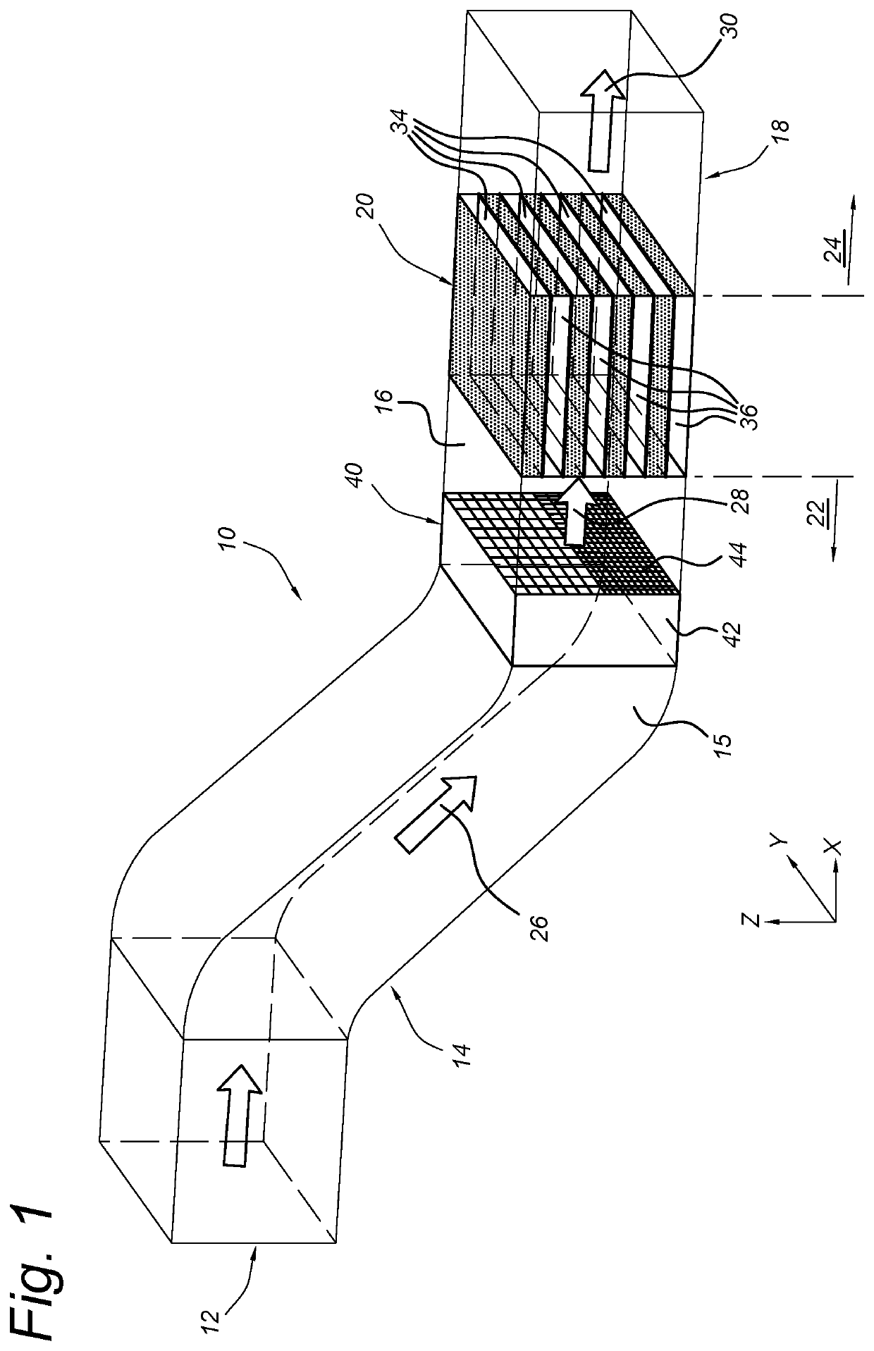
[0030]FIG. 1 schematically shows a perspective view of a portion of a heat transfer system 10. The heat transfer system 10 includes a sequence of conduits 12, which are in fluid communication to define a passage for a flowing gas 26, 28, 30. The conduits 12 are connected to each other, and to a heat exchanger (HE) device 20, and allow the flowing gas to traverse the HE device 20.

[0031]Reference symbol X is used to indicate a longitudinal direction, corresponding with a local direction of macroscopic gas flow. This flow direction X corresponds with the local direction of a sufficiently straight portion of the conduits 12, and may vary along the system of conduits 12. The term “upstream” and “downstream” designate directions opposite to and along with the flow direction X, respectively. Reference symbols Y and Z are used to indicate (local) trans...


PUM


Abstract

Flow conditioner device (40), for use in a heat exchanger system (10). The flow conditioner device includes a honeycomb structure (42) and a mesh (44). The honeycomb structure is configured for rectifying an incoming gas flow (26), and is formed by walls that border channels extending in a flow direction (X) from inlet apertures at a leading surface, to respective outlet apertures at a trailing surface of the honeycomb structure. The mesh is formed by a plurality of wires that extend along further directions (Y, Z) transverse to the flow direction, and which are mutually spaced to define openings. The mesh is attached directly to the honeycomb structure and abuts the second surface, and cross-sectional areas of the openings defined along the further directions vary as a function of position along at least one of the further directions.

Description

TECHNICAL FIELD[0001]The invention relates to a gas flow conditioner device for a heat exchanger, and to a heat exchanger system comprising such a flow conditioner device.BACKGROUND ART[0002]Flow conditioning techniques are employed in various applications, for instance in wind tunnels, flow metering, and heat exchangers. In wind tunnel design, flow conditioning techniques serve to remove secondary flow structures (e.g. swirl) that are caused by the fan or by curves in the wind tunnel, and to reduce turbulent fluctuations in transverse and along stream directions. In flow metering applications, a flow conditioner device may be positioned inside a system of ducts upstream of a measurement section, to promote uniformity of a flow velocity profile at the location of the flow measurement equipment.[0003]In heat exchanger applications, fluid flows with fully developed, stable, and axially symmetric velocity profiles are also desirable. However, a purpose of a heat exchanger is to recoup ...

Claims


Application Information

Patent Timeline
IPC IPC(8): F28F9/02F15D1/02
CPCF28F9/028F15D1/025F28F9/026F28F9/0278F28D9/00F15D1/001F24F2013/088
Inventor DINULESCU, MIRCEAKITZHOFER, JENS
Owner APEX INT HLDG
Why Eureka
Try Eureka