
Side channel compressor for a fuel cell system for conveying and/or compressing a gaseous medium

Pending Publication Date: 2021-05-13
ROBERT BOSCH GMBH
View PDF9 Cites 0 Cited by
  • Summary
  • Abstract
  • Description
  • Claims
  • Application Information

AI Technical Summary

Benefits of technology

The patent describes a new type of side channel compressor for a fuel cell system that is designed to be compact and space-saving. The compressor is made up of a stator and rotor, with both components being narrow in the rotation axis direction. This reduces the amount of structural space needed, making it ideal for use in vehicles or other space-limited environments. The compressor is designed to prevent ice bridges from forming between components, which can cause damage and reduce its effectiveness. By shaking the rotor and compressor wheel, the compressor can effectively destroy any ice bridges, improving its cold start capability and reducing the likelihood of failure.

Problems solved by technology

Such ice bridges may make more difficult and / or completely prevent starting, in particular a cold start, of the fuel cell system, in particular the side channel compressor.
When the vehicle and consequently the fuel cell system is started, this can further lead, in the event of excessive ice bridge formation, to the drive becoming blocked, whereby the rotating components, in particular the compressor wheel, can become damaged and / or a starting of the system is made more difficult or delayed or completely prevented.

Method used


Image

  • Side channel compressor for a fuel cell system for conveying and/or compressing a gaseous medium
  • Side channel compressor for a fuel cell system for conveying and/or compressing a gaseous medium
  • Side channel compressor for a fuel cell system for conveying and/or compressing a gaseous medium

Examples


Embodiment Construction

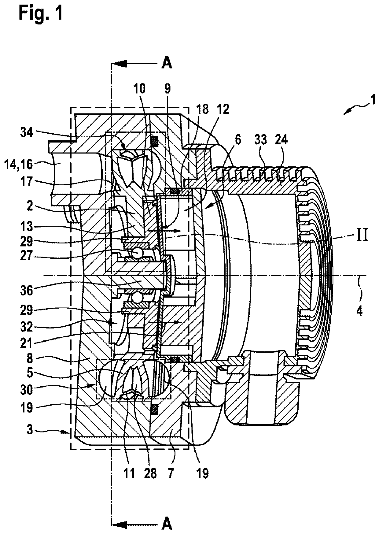
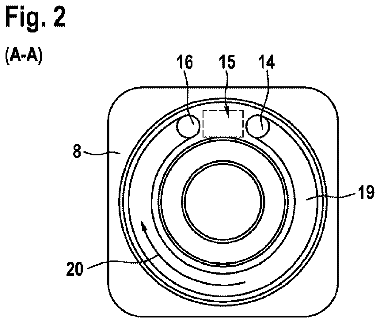
[0027]The illustration according to FIG. 1 shows a longitudinal section through a side channel compressor 1 which is proposed according to the invention and which is formed in a rotationally symmetrical manner with respect to a rotation axis 4.

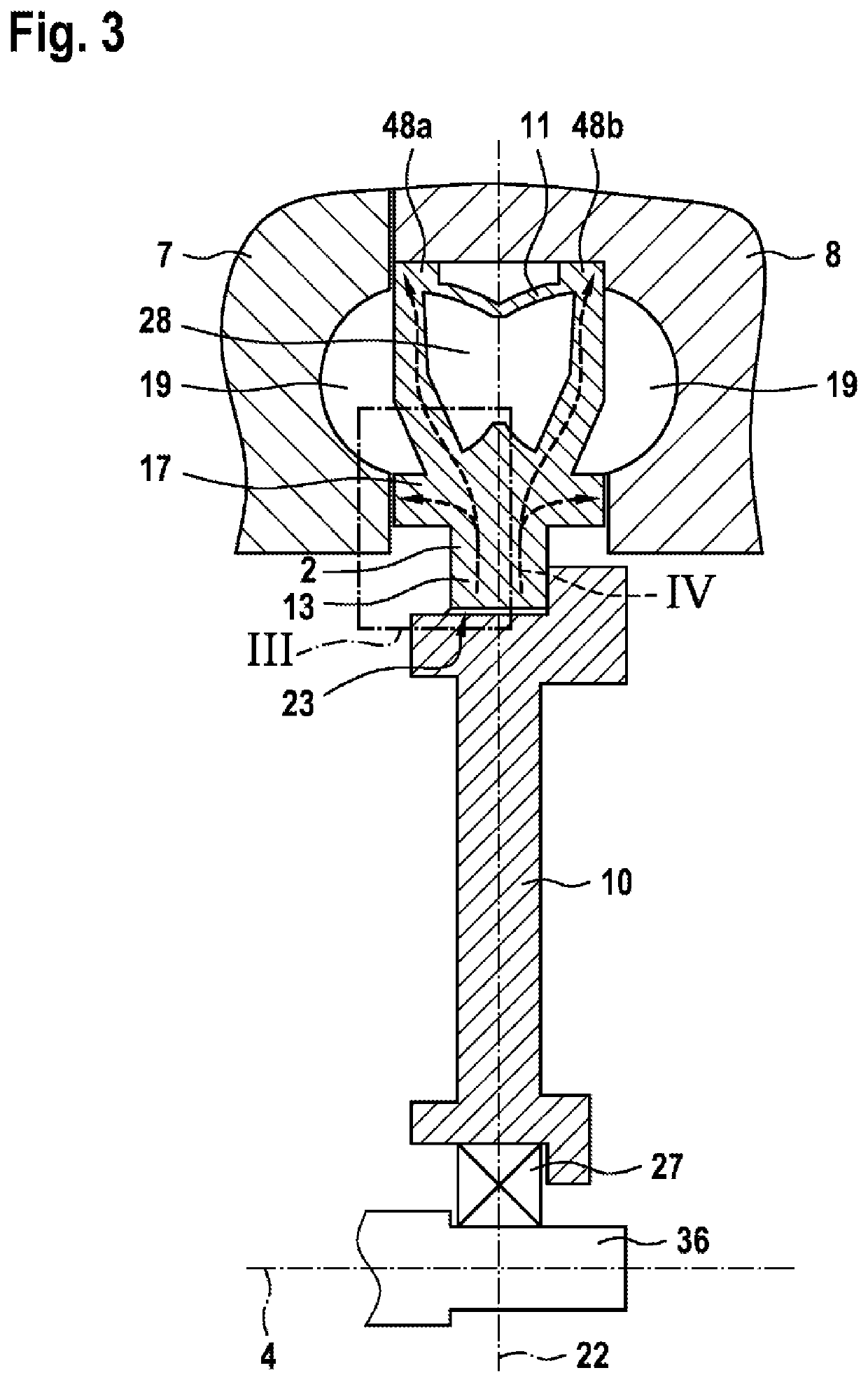
[0028]In this instance, the side channel compressor 1 has a compressor wheel 2 which is constructed in particular as a closed disk-like compressor wheel 2 and which is supported in a housing 3 so as to be able to be rotated about the horizontally extending rotation axis 4. In this instance, a drive 6, in particular an electric drive 6, acts as a rotary drive 6 of the compressor wheel 2. The drive 6 is in this instance in particular constructed as an axial field electric motor 6, wherein it has a stator 12 and a rotor 10, wherein the stator 12 and the rotor 10 are formed so as to extend in a disk-like manner around the rotation axis 4 and wherein the stator 12 is arranged in the direction of the rotation axis 4 beside the rotor 10. In this inst...


PUM


Abstract

The invention relates to a side channel compressor (1) for a fuel cell system for conveying and / or compressing a gas, particularly hydrogen, comprising a housing (3) and a drive (6), wherein the housing (3) has a housing upper part (7) and a housing lower part (8), a compressor chamber (30) which is circulating in the housing (3) about an axis of rotation (4) and has at least one peripheral side channel (19), a compressor wheel (2) located in the housing (3), which is rotatably arranged about an axis of rotation (4) and is driven by the drive (6), said compressor wheel (2) comprising blades (5) arranged on the periphery thereof in the region of the compressor chamber (30), and comprising respectively a gas inlet opening (14) embodied on the housing (3) and a gas outlet opening (16) which are fluidically interconnected via the compressor chamber (30), in particular the at least one side channel (19). According to the invention, the drive (6) is designed as an axial field electric motor (6) which has a stator (12) and a rotor (10), wherein the stator (12) and the rotor (10) have a disc-shaped design and are formed so as to move about the axis of rotation (4), and wherein the stator (12) is arranged next to the rotor in the direction of the axis of rotation (4).

Description

BACKGROUND OF THE INVENTION[0001]The present invention relates to a side channel compressor for a fuel cell system for conveying and / or compressing a gaseous medium, in particular hydrogen, which is provided in particular for use in vehicles with a fuel cell drive.[0002]In the vehicle sector, in addition to liquid fuels, gaseous fuels will also take on increasing significance in the future. Particularly in vehicles with a fuel cell drive, hydrogen gas flows have to be controlled. The gas flows are in this instance no longer controlled in a discontinuous manner as with the injection of liquid fuel, but instead the gas is removed from at least one high-pressure tank and directed via a supply line of a medium-pressure pipe system to an ejector unit. This ejector unit leads the gas via a connection line of a low-pressure line system to a fuel cell. After the gas has flowed through the fuel cell, it is directed via a return line back to the ejector unit. In this instance, the side channe...

Claims


Application Information

Patent Timeline
IPC IPC(8): F04D23/00F04D29/58F04D29/08F04D29/18F04D27/00
CPCF04D23/008F04D29/58F04D27/00F04D29/18F04D29/08F04D25/0653H01M8/04097H01M8/04253Y02E60/50F04D29/5806F04D29/584F04D27/0292F04D29/053F04D29/26F04D29/284
Inventor HERO, ALEXANDERMERZ, ARMIN
Owner ROBERT BOSCH GMBH
Learn More