
Method for preparing catalytic nanoparticles, catalyst surfaces, and/or catalysts

a technology of catalytic nanoparticles and catalyst surfaces, applied in the field of catalytic particles, catalyst surfaces, or catalysts, can solve the problems of catalytic nanoparticles, catalyst amorphisation, or support, and achieve the effect of improving catalytic properties and high-efficiency treatment of catalytic starting materials

Inactive Publication Date: 2021-05-06
AGC GLASS EUROPE SA +3
View PDF1 Cites 0 Cited by
  • Summary
  • Abstract
  • Description
  • Claims
  • Application Information

AI Technical Summary

Benefits of technology

This patent describes a method for making catalyst particles that are more uniform in size and have better control over their catalytic properties. This allows for more efficient use of the catalyst and results in a more uniform catalytic converter. The method reduces the amount of excess catalyst material needed and minimizes the amount of dust generated during the process. Excessive melting and fragmentation of the catalyst material is also reduced. The method also leads to improved penetration depth of the catalyst material, which results in better treatment of the material and improved catalytic properties. The energy of the ions in the ion beam can influence the penetration depth, and changing the atomic number and energy of ions can lead to improved catalytic properties. Overall, this method provides a more efficient and effective way to produce highly effective catalyst particles.

Problems solved by technology

While the exact reasons behind the observed improvements are still not completely understood, it appears that the inventive method can cause defects in and / or on the catalyst, the catalyst particles and / or support nanoparticles that lead to the observed improvements.
The inventive method can cause amorphisation of the catalyst, the catalytic nanoparticles, or support.

Method used


Image

  • Method for preparing catalytic nanoparticles, catalyst surfaces, and/or catalysts
  • Method for preparing catalytic nanoparticles, catalyst surfaces, and/or catalysts

Examples


example 1

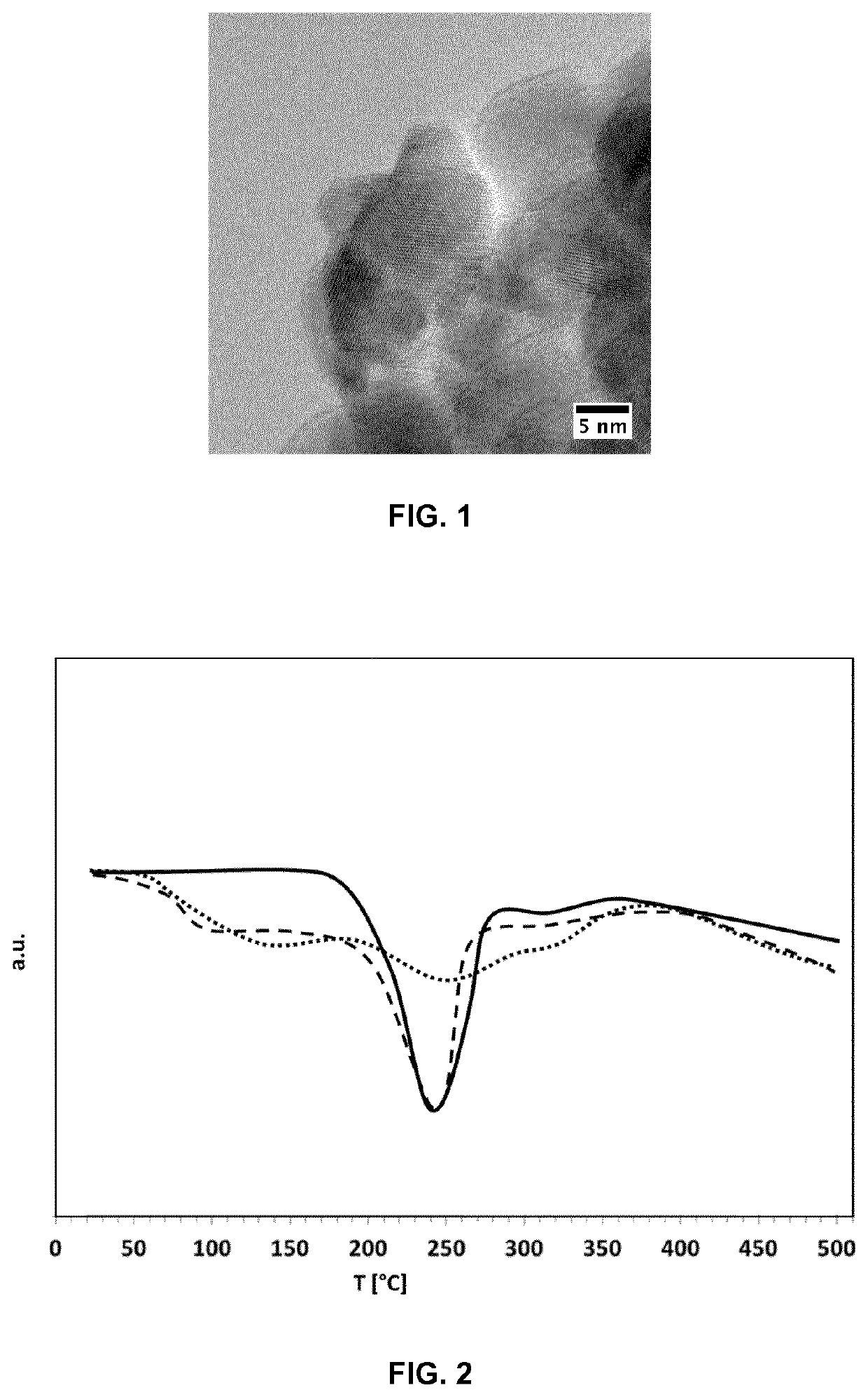
[0246]Starting material 1, 600 mg Pt / Ce0.68Zr0.32O2, was placed in a microimplantor designed by the company Quertech, now Ionics, including an ECR (Electron Cyclotron Resonance) ion source powered by a 10 GHz and 50 W HF amplifier, and an ion extraction system of 10 kV (kiloVolt). The plasma of the ion source was confined by permanent magnets allowing the production of monocharged and multicharged ions).

[0247]600 mg of Pt / Ce0.68Zr0.32O2 catalyst particles agglomerated in powder form was spread over a surface of 400 cm2 and submitted to 16 treatments with a partial dose of ions of 5×10¹⁵ ions / cm2, between each treatment the powder was mixed and then spread again on the same surface of 400 cm2. Due to the poor distribution mentioned above only about 120 to 200 cm2 are effectively covered by the starting material. The surface density of the catalyst particles is thus 0.003 to 0.005 g / cm2 and the resulting dosage is between 1.60×10¹⁹ to 2.67×10¹⁹ ions / g. The dosage is the same for ex...

example 2

[0248]Starting material 2, 600 mg of Pt / γ-Al2O3 catalyst particles agglomerated in powder form, was spread over a surface of 400 cm2 and submitted to 16 treatments with a partial dose of ions of 5×10¹⁵ ions / cm2, between each treatment the powder was mixed and then spread again on the same area of 400 cm2. The treatment was performed with mono and multicharged nitrogen ions (58% N+, 32% N2 +, 9% N3+, 1% N4+) extracted by an extraction voltage of 35 kV, i.e. with a mean charge state of 1.53 and mean energy Eavr equal to 53 keV. The moving of the ion beam consisted in a succession of round-trips on a surface treatment of 68×28 cm2 with a speed of 80 mm / s, each round trip was performed with an advancement step corresponding to a fraction of the ion beam diameter of 30%, in other words corresponding to an absolute shift of 6.75 mm (30% of 22.5 mm). The ion beam current to ion beam cross-section area ratio was 2.52 μA / mm2. The pressure in the treatment chamber was 10−5 mbar.

example 3

[0249]Starting material 3, 600 mg of Ce0.68Zr0.32O2 support nanoparticles in agglomerated powder from, was spread over an area of 400 cm2 and submitted to 16 treatments with a partial dose of ions of 5×10¹⁵ ions / cm2, between each treatment the powder was mixed and then spread again on the same area of 400 cm2. The treatment was performed with mono and multicharged nitrogen ions (58% N+, 32% N2+, 9% N3+, 1% N4+) extracted by an extraction voltage of 35 kV, i.e. with a mean charge state of 1.53 and mean energy Eavr equal to 53 keV. The moving of the ion beam consisted in a succession of round-trips covering a total area of 68×28 cm2 with a speed of 80 mm / s, each round trip was performed with an advancement step corresponding to a fraction of the ion beam diameter of 30%, in other words corresponding to an absolute shift of 6.75 mm (30% of 22.5 mm). The ion beam current to ion beam cross-section area ratio was 2.52 μA / mm2. The pressure in the treatment chamber was 10−5 mbar.


PUM

PropertyMeasurementUnit
energyaaaaaaaaaa
energyaaaaaaaaaa
atomic numberaaaaaaaaaa

Abstract

A method for preparing catalyst particles that includes providing a catalyst starting material, an ion beam, and an electrostatic charge reduction device selected from a source of UV light, a source of X-rays, an electron beam, and an electrically grounded catalytic starting material carrier. The method further includes implanting the catalyst starting material with an ion beam dose primarily made of monocharged or monocharged and multicharged ions with an energy of the monocharged ions in the ion beam from at least 10 keV to at most 100 keV thereby obtaining a catalyst. The obtained catalyst particles particles are useful in NOx, CO, and / or HC emission reduction devices, fuel cells, or catalysts in chemical reactions.

Description

FIELD OF THE INVENTION[0001]The invention relates to the preparation of catalytic particles, catalyst surfaces, or catalysts, more in particular to the preparation of catalytic particles, catalyst surfaces, or catalysts suitable to be used in pollution emission treatments of exhaust gasses, for example from vehicle combustion engines.BACKGROUND OF THE INVENTION[0002]Currently catalyst particles are known and used for the reduction of pollution emission. Typically, catalyst particles are arranged in a catalytic converter, which is fluidly connection to the exhaust of a vehicle combustion engine.[0003]As the catalytic material is often rare, expensive and / or environmentally unfriendly at the end of its life cycle, there is a demand to elevate or to maximise the catalytic activity of a certain amount of catalytic material.[0004]There is a further demand for production methods that have a high yield and preferably do not generate a lot of waste material, e.g. catalytic material that is ...

Claims


Application Information

Patent Timeline
Patent Type & Authority Applications(United States)
IPC IPC(8): B01J23/42B01J23/10B01J21/04B01J35/00B01J37/34C23C14/48
CPCB01J23/42B01J23/10C23C14/48B01J35/0013B01J37/347B01J21/04B01J23/44B01J23/464B01J29/005B01J37/0072B82Y30/00B82Y40/00B01J23/002B01J37/0027B01J37/038C23C14/18B01J35/23B01J35/50
Inventor BUSARDO, DENISVENTELON, LIONEL
Owner AGC GLASS EUROPE SA
Learn More