Automated Analysis System

a technology of automatic analysis and analysis system, applied in the direction of material analysis, instruments, etc., can solve the problems of limited personnel, complicated screen hierarchy, tight routine operations, etc., and achieve the effect of reducing the status of automatic analyzers and improving working efficiency

Active Publication Date: 2021-04-29
HITACHI HIGH-TECH CORP
View PDF0 Cites 1 Cited by
  • Summary
  • Abstract
  • Description
  • Claims
  • Application Information

AI Technical Summary

Benefits of technology

[0022]In the inventions disclosed in the present application, the brief description of the effects obtained by the representative ones is as follows.
[0023](1) The number of man-hours in the confirmation of the status of the automatic analyzer can be reduced.
[0024](2) From the effect (1), the working efficiency can be improved.

Problems solved by technology

Nowadays, as for the content displayed on the desktop PC screen, information volumes displayed on the screen are increasing in association with the multifunction and sophistication of the automatic analyzer, and the screen hierarchy also becomes complicated.
On the other hand, when attention is paid to inspection operations, in addition to an increase in the amount of automatic analysis processing and a prompt response to an emergency sample, routine operations become tight due to the influence of a reduction in workforce, for example.
However, since personnel is limited, one operator virtually takes charge of operating a plurality of devices.

Method used


Image

  • Automated Analysis System
  • Automated Analysis System
  • Automated Analysis System

Examples


Embodiment Construction

[0034]In the entire drawings for explaining an embodiment, the same members are designated with the same reference signs in principle, and the duplicated description is omitted.

[0035]In the following, an embodiment will be described in detail.

[0036]Exemplary Configuration 1 of Automated Analysis System

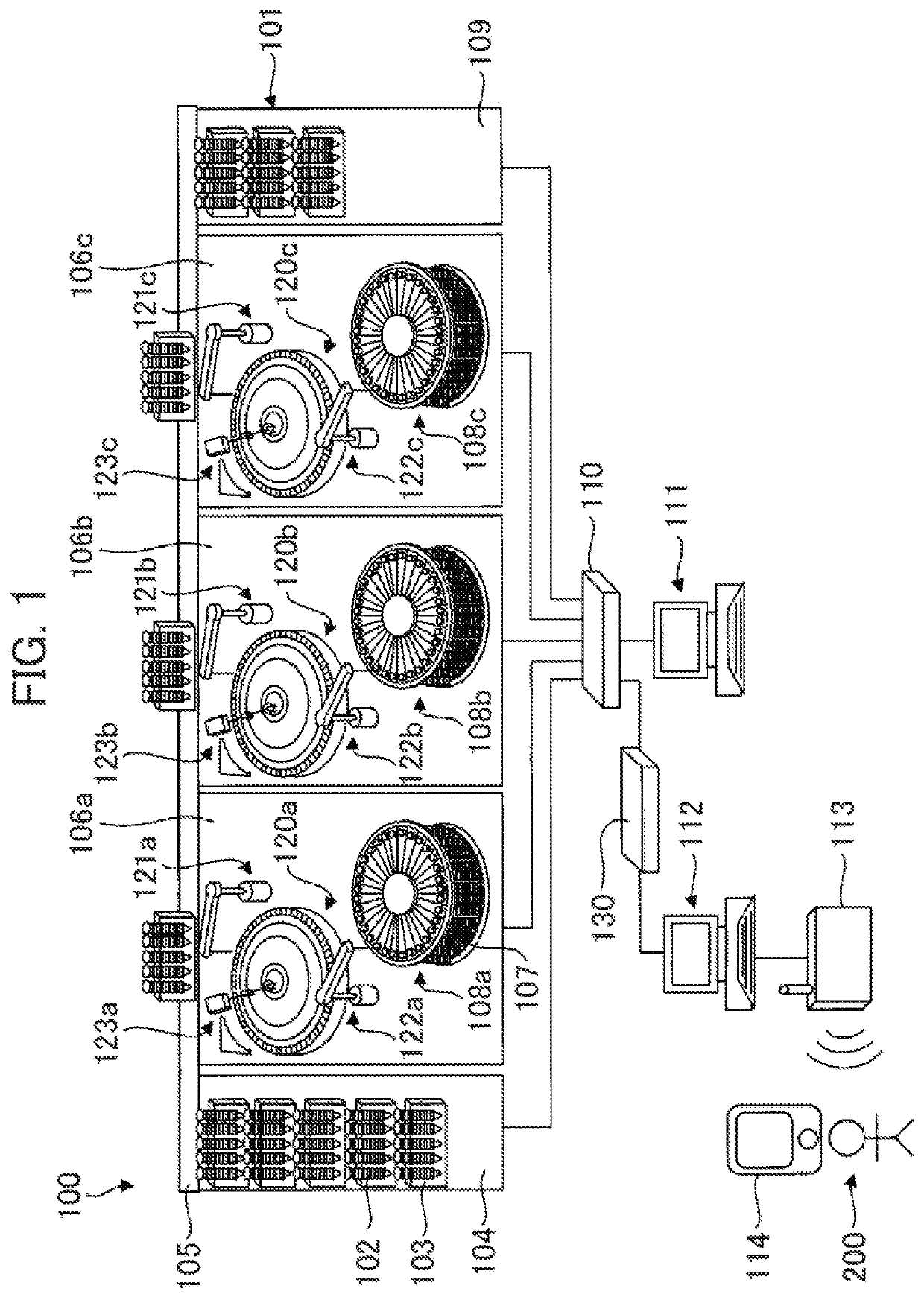
[0037]FIG. 1 is an illustration showing an exemplary configuration of an automated analysis system according to an embodiment.

[0038]In the automated analysis system shown in FIG. 1, the overall structure having one automatic analyzer is schematically shown.

[0039]As shown in FIG. 1, an automated analysis system 100 has an automatic analyzer 101, a communication device 110, an operation unit PC 111, an information management PC 112, a wireless device 113, and a communication device 130.

[0040]The automatic analyzer 101 has a sample input unit 104, analysis units 106a, 106b, and 106c, a transfer line 105, and a sample housing unit 109, for example. The automatic analyzer 101 is connected t...


PUM

PropertyMeasurementUnit
timeaaaaaaaaaa
volumesaaaaaaaaaa
absorbanceaaaaaaaaaa

Abstract

Work, such as status confirmation, in a plurality of automatic analyzers is efficiently performed. In an automated analysis system, a tablet terminal 114 has a terminal information management unit 210 and a terminal display unit 208. A terminal information management unit 210 acquires device information showing the state status of a device from automatic analyzers 101a to 101d, and generates a status confirmation screen showing the device status of the automatic analyzer. A terminal display unit 208 displays the status confirmation screen. The status confirmation screen has a status information screen showing the device status of one automatic analyzer and a device switch button configured to switch the status information screen to a status information screen corresponding to another other automatic analyzer. When the switch button is selected, the terminal information management unit 210 generates a status confirmation screen for an automatic analyzer corresponding to the selected switch button, and displays the status confirmation screen on the display unit.

Description

TECHNICAL FIELD[0001]The present invention relates to an automated analysis system, and more specifically to a technique that is effective to confirm the status of a plurality of analyzers.BACKGROUND ART[0002]As a device that performs the qualitative and quantitative analysis of biological samples, such as blood and urine, (in the following, simply referred to as a sample), an automatic analyzer is widely known. The automatic analyzer is provided with an operation unit.[0003]The operation unit executes analysis and maintenance, and confirms the result of the execution, displays the unique information or remaining amount information of a reagent, or notifies an abnormality that occurs on a device by alarm, for example.[0004]For the operation unit, a desktop personal computer (in the following, simply referred to as a desktop PC) is mainly used. In some cases, a tablet terminal, for example, is sometimes used, other than the desktop PC attached to the device.[0005]The tablet terminal ...

Claims


Application Information

Patent Timeline
Patent Type & Authority Applications(United States)
IPC IPC(8): G01N35/02G01N35/10G01N35/00
CPCG01N35/025G01N35/00732G01N35/0092G01N35/1002G01N2035/0091G01N2035/009G01N2035/00881G01N35/00871G01N35/00712
Inventor SHIBUYA, SATOSHIHANAWA, TOSHIHIDEKASAMA, MIKIO
Owner HITACHI HIGH-TECH CORP
Why Eureka
Try Eureka