
Magnetic core material for electrophotographic developer, carrier for electrophotographic developer, developer, method for producing magnetic core material for electrophotographic developer, method for producing carrier for electrophotographic developer, and method for producing developer

Active Publication Date: 2021-03-18
POWDERTECH
View PDF0 Cites 0 Cited by
  • Summary
  • Abstract
  • Description
  • Claims
  • Application Information

AI Technical Summary

Benefits of technology

The present invention provides a magnetic core material for electrophotographic developer that has small environmental dependence of the electric resistance and can effectively suppress the carrier scattering. By controlling the contents of specific anion components, a carrier core material with good image stability can be formed. The invention also includes a method for producing the magnetic core material, the carrier for electrophotographic developer, and the developer.

Problems solved by technology

As described above, the attempts for improving the carrier characteristics by controlling a shape of carrier core material or an amount of impurities have been known, but, there is a problem in that the carrier characteristics are not sufficient for further demands of high image quality and high speed printing in recent years.
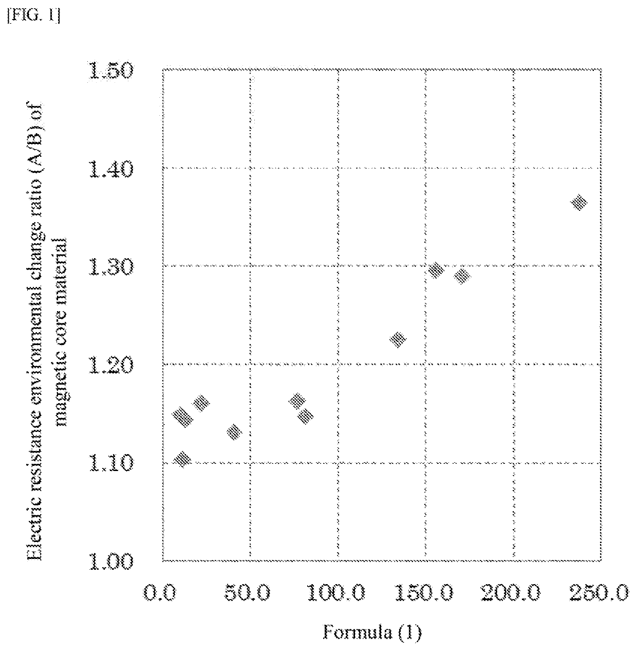
This is because when the environmental dependence of the electric resistance is large, the image characteristics such as image density or fog are significantly changed depending on usage environment so that stable image characteristics cannot be obtained.
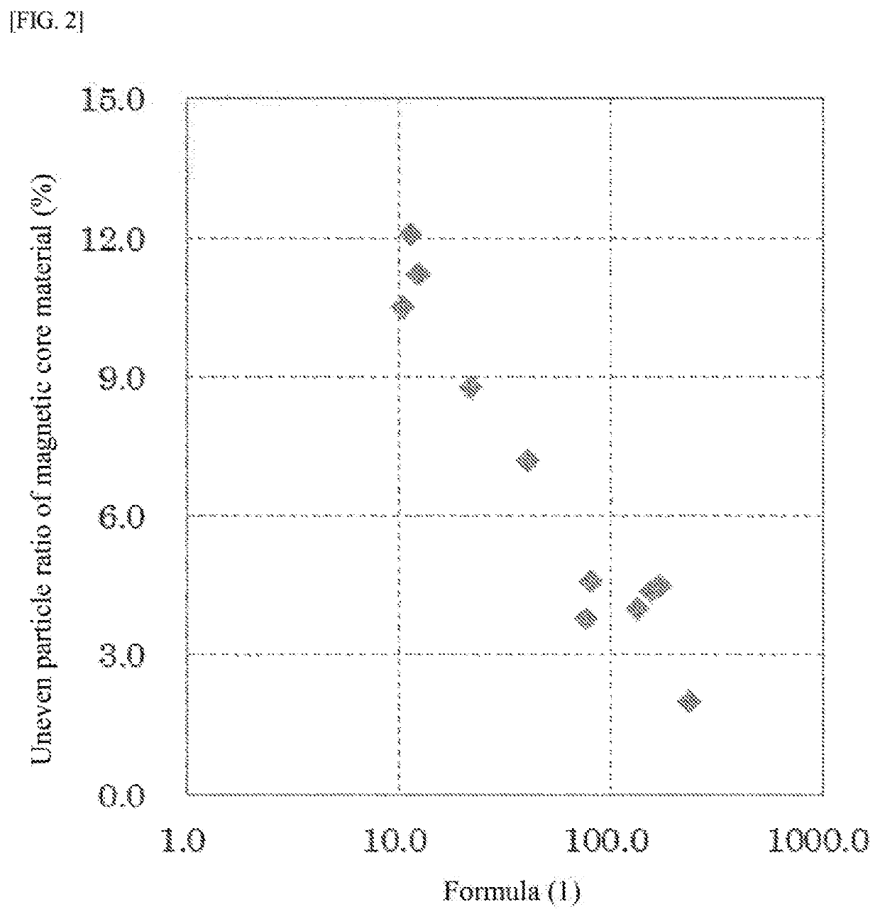
Furthermore, this is because when the carrier scattering is large, white spots occur on the image or the carrier scattered damages a photoreceptor.

Method used


Image

  • Magnetic core material for electrophotographic developer, carrier for electrophotographic developer, developer, method for producing magnetic core material for electrophotographic developer, method for producing carrier for electrophotographic developer, and method for producing developer
  • Magnetic core material for electrophotographic developer, carrier for electrophotographic developer, developer, method for producing magnetic core material for electrophotographic developer, method for producing carrier for electrophotographic developer, and method for producing developer

Examples


example 1

(1) Production of Magnetic Core Material

[0065]Raw materials were weighed so as to attain a composition ratio after sintering being 20% by mole of MnO and 80% by mole of Fe2O3, water was added thereto, and the mixture was pulverized and mixed by a wet ball mill for 5 hours, dried, and then maintained at 950° C. for one hour to perform calcination. As the MnO raw material and the Fe2O3 raw material, 2.7 kg of trimanganese tetraoxide and 22.3 kg of Fe2O3 were used, respectively.

(1-1) Pulverization of Calcined Product

[0066]Water was added to the calcined product thus-obtained, the mixture was pulverized by a wet ball mill for 4 hours, and the resulting slurry was pressed and dehydrated by a belt press machine. To the cake obtained was added water, and the mixture was pulverized again by a wet ball mill for 4 hours to obtain slurry 1.

(1-2) Granulation

[0067]To slurry 1 obtained was added PVA (polyvinyl alcohol) (aqueous 20% by weight solution) as a binder in an amount of 0.2% by weight wi...

example 2

(1) Production of Magnetic Core Material

[0084]The magnetic core material and carrier were produced in the following manner. Namely, raw materials were weighed so as to attain a composition ratio after sintering being 40.0% by mole of MnO, 10.0% by mole of MgO and 50.0% by mole of Fe2O3, and with respect to the 100 parts by weight of these metal oxides, 1.5 parts by weight of ZrO2 was weighed and added. As the raw material, 16.9 kg of Fe2O3, and as the MnO raw material, the MgO raw material and the ZrO2 raw material, 6.5 kg of trimanganese tetraoxide, 1.2 kg of magnesium hydroxide and 0.4 kg of ZrO2 were used, respectively.

(1-1) Pulverization of Calcined Product

[0085]The mixture was pulverized and mixed by a wet ball mill for 5 hours, dried, and then maintained at 950° C. for one hour to perform calcination. Water was added to the calcined product thus-obtained, the mixture was pulverized by a wet ball mill for 4 hours, and the resulting slurry was dehydrated by a screw press machine...

example 3

(1) Production of Magnetic Core Material

[0090]The magnetic core material and carrier were produced in the following manner.

[0091]Namely, raw materials were weighed so as to attain a composition ratio after sintering being 10.0% by mole of MnO, 13.3% by mole of Li2O and 76.7% by mole of Fe2O3, and water was added so as to attain a solid content of 50%. Furthermore, an aqueous lithium silicate solution with 20% in terms of SiO2 was added thereto so as to attain an amount of Si being 10,000 ppm with respect to the solid content. As the raw material, 21.9 kg of Fe2O3, and as the MnO raw material and the Li2O raw material, 1.4 kg of trimanganese tetraoxide and 1.8 kg of lithium carbonate were used, respectively.

(1-1) Pulverization of Calcined Product

[0092]The mixture was pulverized and mixed by a wet ball mill for 5 hours, dried, and then calcined at 1,000° C. in the air. Water was added to the calcined product thus-obtained, the mixture was pulverized by a wet ball mill for 4 hours, and...


PUM


Abstract

To provide a magnetic core material for electrophotographic developer and carrier for electrophotographic developer which have small environmental dependence of the electric resistance, can suppress the carrier scattering, and can stably provide good images; a developer contains the carrier; a method for producing the magnetic core material for electrophotographic developer; a method for producing the carrier for electrophotographic developer, and a method for producing the developer.The magnetic core material for electrophotographic developer, satisfying a value of Formula (1): a+b×10+c+d+e+f, being from 20 to 150, when a fluoride ion amount is denoted by a (ppm), a chloride ion amount is denoted by b (ppm), a bromide ion amount is denoted by c (ppm), a nitrite ion amount is denoted by d (ppm), a nitrate ion amount is denoted by e (ppm), and a sulfate ion amount is denoted by f (ppm), which are measured by a combustion ion chromatography method.

Description

TECHNICAL FIELD[0001]The present invention relates to a magnetic core material for electrophotographic developer, a carrier for electrophotographic developer, a developer, a method for producing the magnetic core material for electrophotographic developer, a method for producing the carrier for electrophotographic developer, and a method for producing the developer.BACKGROUND ART[0002]The electrophotographic development method is a method in which toner particles in a developer are made to adhere to electrostatic latent images formed on a photoreceptor to develop the images. The developer used in this method is classified into a two-component developer composed of a toner particle and a carrier particle, and a one-component developer using only a toner particle.[0003]As a development method using the two-component developer composed of a toner particle and a carrier particle among those developers, a cascade method and the like were formerly employed, but a magnetic brush method usi...

Claims


Application Information

Patent Timeline
IPC IPC(8): G03G9/107G03G9/08G03G9/113
CPCG03G9/1085G03G9/1075G03G9/1132G03G9/0817G03G9/1131G03G9/081G03G9/1133G03G9/1136
Inventor SAWAMOTO, HIROKIUEMURA, TETSUYA
Owner POWDERTECH
Learn More