
Electronic device having heat dissipation function

a technology of electronic equipment and heat dissipation function, which is applied in the direction of lighting and heating apparatus, modifications of conduction heat transfer, and semiconductor/solid-state device details. it can solve the problems of low heat dissipation efficiency, breakdown of electronic equipment, and difficulty in heat dissipation design, so as to improve heat dissipation efficiency and heat dissipation performance of components. , the effect of high thermal resistan

Active Publication Date: 2021-03-11
LG ELECTRONICS INC
View PDF0 Cites 1 Cited by
  • Summary
  • Abstract
  • Description
  • Claims
  • Application Information

AI Technical Summary

Benefits of technology

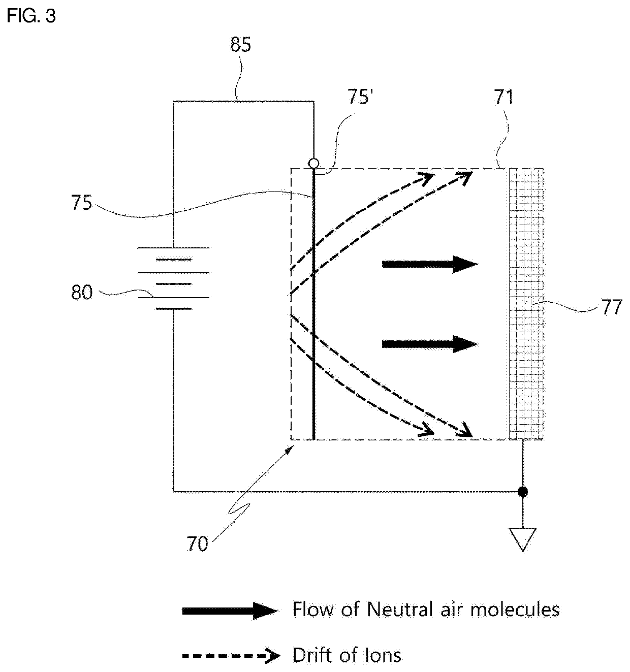
The patent aims to solve the problem of excessive heating in electronic devices, which can cause damage and malfunction. The solution involves using an ionic wind generated by a wire electrode and a collector electrode to cool the heating element. This approach results in high heat dissipation performance in a narrow installation space and low noise / vibration compared to cooling fans. Therefore, the patent can be applied to various electronic devices that require low noise / vibration.

Problems solved by technology

When the heat is not sufficiently discharged to the outside, the performance and lifespan of the electronic equipment may be lowered and the deformation caused by the heat may cause the breakdown of the electronic equipment.
However, although the inside of the roof of the vehicle is easy to be heated by external heat, the inside of the roof is very narrow, so there is a problem that it is difficult to install therein a high-performance heat dissipation means such as a heat dissipation fan.
Accordingly, miniaturization of the electronic device is not easy.
In particular, the communication module described above is not only installed in a narrow place but also has a severe heat generating condition.
Accordingly, the communication module is required to have a small size and high heat dissipation performance, but the ionic wind generator does not provide as much air volume as the air volume of a heat dissipation fan.
Accordingly, it is difficult to implement a heat-dissipating device that satisfies all of these conditions.

Method used


Image

  • Electronic device having heat dissipation function
  • Electronic device having heat dissipation function
  • Electronic device having heat dissipation function

Examples


first embodiment

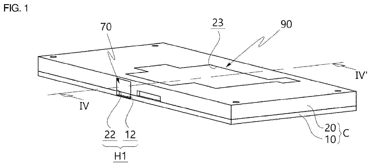
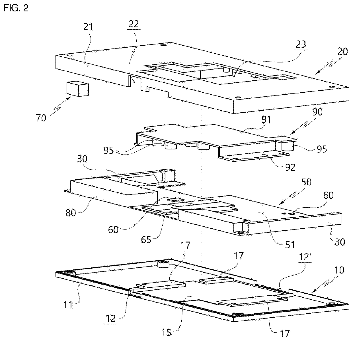
[0041]FIG. 1 is a perspective view illustrating an electronic device having heat dissipation function according to the present disclosure, and FIG. 2 is an exploded perspective view illustrating components constituting the electronic device according to the first embodiment illustrated in FIG. 1.

[0042]As illustrated in FIGS. 1 and 2, a casing C constitutes an outer surface and framework of the electronic device. The casing C may be made of a metal or nonmetallic material and includes an inner space S which is empty (see FIG. 4) therein. A circuit board 50, the heat dissipation means 70, and the heating element 60, which will be described hereinbelow, are installed in the inner space S. In the embodiment, the casing C has a closed shape, but may have an open shape in a portion thereof.

[0043]The casing C includes a lower casing 10 and an upper casing 20. When the lower casing 10 is assembled with the upper casing 20, the inner space S is defined therebetween. In the embodiment, each o...

second embodiment

[0079]The heat exchange part is a heat dissipation protrusion part surrounding the surface of the heat dissipation bridge 95 and protruding therefrom, and includes heat dissipation plates 97 in a As illustrated in FIG. 6B, each of the heat dissipation plates 97 has a thin ring shape to surround an outer circumferential surface of the heat dissipation bridge 95 of a cylindrical shape. The heat dissipation plate 97 is provided in a direction parallel to a direction (a direction of arrow ① of FIG. 6A) in which the ionic wind flows. Accordingly, the heat dissipation plate does not block the flow of the ionic wind and increases the surface area of heat dissipation bridge which exchanges heat with the ionic wind. In the embodiment, each of the multiple heat dissipation plates 97 is spaced apart from each other and laminated at a different height, so a groove part 97′ is provided therebetween.

[0080]The heat dissipation plate 97 and the groove part 97′ create turbulence in the ionic wind. ...

third embodiment

[0081]Next, FIGS. 7A and 7B illustrate the heat dissipation bridge 95. A heat dissipation block 97 is combined with the heat dissipation bridge 95 illustrated in FIGS. 7A and 7B. The heat dissipation block 97 may be regarded as a kind of the heat exchange part and has a cross-sectional area larger than a cross sectional area of the heat dissipation bridge 95. In the embodiment, the heat dissipation block 97 has a cylindrical shape. Alternatively, when the shape of the heat dissipation bridge 95 is a polygonal column shape, the shape of the heat dissipation block 97 may be changed to the shape corresponding thereto.

[0082]The heat dissipation block 97 is made of a porous metal foam material. The porous metal foam material as a porous structure corresponds to a foam metal. The heat dissipation block 97 is made of a metal material containing multiple pores, and such a metal foam may have a high specific surface area. Accordingly, the heat dissipation block 97 increases the heat exchange...


PUM


Abstract

An electronic device having heat dissipation function is proposed. The electronic device includes: a heating element (60) installed in a casing (C); a heat dissipation means (70) causing an ionic wind to flow into an inner space (S) of the casing (C); and a heat dissipation bridge (95). The heat dissipation bridge (95) exchanges heat with the ionic wind flowing in the inner space (S) by protruding in a direction of the heating element (60) and at least a portion of the heat dissipation bridge is connected to a heat sink and transfers heat received from the heating element (60) to the heat sink. Accordingly, two means of the heat dissipation means (70) and the heat dissipation bridge (95) simultaneously cool the heating element (60), so cooling efficiency is improved.

Description

CROSS REFERENCE TO RELATED APPLICATION[0001]The present application claims priority to Korean Patent Application No. 10-2019-0112377, filed Sep. 10, 2019, the entire contents of which is incorporated herein for all purposes by this reference.BACKGROUND OF THE INVENTIONField of the Invention[0002]The present disclosure generally relates to an electronic device. More particularly, the present disclosure relates to an electronic device having a heat dissipation function, wherein an ionic wind is used to reduce the temperature of a heating element.Description of the Related Art[0003]In recent years, with the trend of miniaturization of electronic equipment, the integration density of an electronic device is increasing, and accordingly, heat generated from the electronic equipment is increased. When the heat is not sufficiently discharged to the outside, the performance and lifespan of the electronic equipment may be lowered and the deformation caused by the heat may cause the breakdown ...

Claims


Application Information

Patent Timeline
Patent Type & Authority Applications(United States)
IPC IPC(8): H05K7/20F28F13/16
CPCH05K7/20009H05K7/20409F28F13/16H01L23/467H05K7/20154H05K7/20136H05K7/20509H01T23/00H01L23/367H01L23/3733
Inventor JEONG, MINWOORYU, CHUN HYUKSHIN, JONGKILKIM, BONGJUNPARK, MINJAE
Owner LG ELECTRONICS INC
Learn More