Lateral Spine Plate With Collapsible Vertebral Attachment Arms

a technology of lateral spine plate and attachment arm, which is applied in the field of orthopedic implants, can solve the problems of increasing the chance of surgical trauma, and achieve the effect of lowering the profile heigh

Active Publication Date: 2021-03-11
LIFE SPINE INC
View PDF11 Cites 0 Cited by
  • Summary
  • Abstract
  • Description
  • Claims
  • Application Information

AI Technical Summary

Benefits of technology

[0008]A lateral spine plate for a lateral spinal interbody cage has one or more collapsible / folding arms configured for attachment to one or more vertebrae, the ability of the one or more arms to collapse / fold allows the lateral spine plate to be inserted / implanted at a lower profile height than traditional lateral spine plates. The lateral spine plate is also modular respective to a standard spinal interbody cage allowing securement to the interbody cage when needed.
[0012]In one form, the attachment pin has a compressible arrow tip that compresses within an insertion hole of the interbody cage and, upon reaching an inner wall of a window of the interbody cage, will expand and prevent disassociation. In one form, the shaft of the attachment pin includes threads that mate with threads of the insertion hole of the interbody cage to provide additional engagement with the interbody cage. The length of the attachment pin compressible arrow tip and threads provide the ability to adjust offset distance of the lateral spine plate from the interbody cage to allow for preferred placement of the interbody cage within the disc space and / or due to anatomical variations (e.g. osteophytes) that require accommodation.

Problems solved by technology

Such lateral spine plates are generally large and thus have a large profile, thereby increasing the chance of surgical trauma.

Method used


Image

  • Lateral Spine Plate With Collapsible Vertebral Attachment Arms
  • Lateral Spine Plate With Collapsible Vertebral Attachment Arms
  • Lateral Spine Plate With Collapsible Vertebral Attachment Arms

Examples


Embodiment Construction

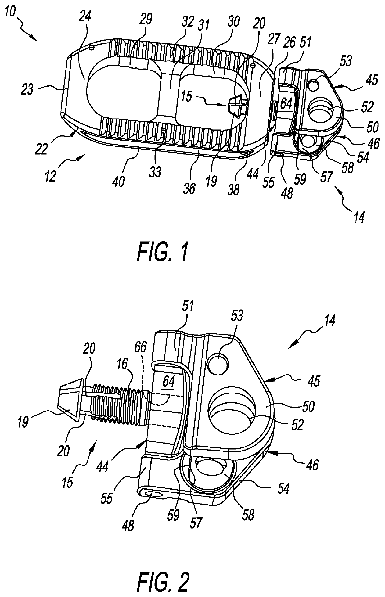
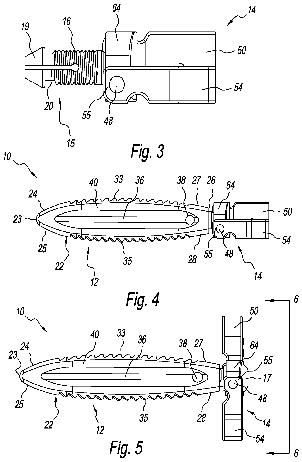
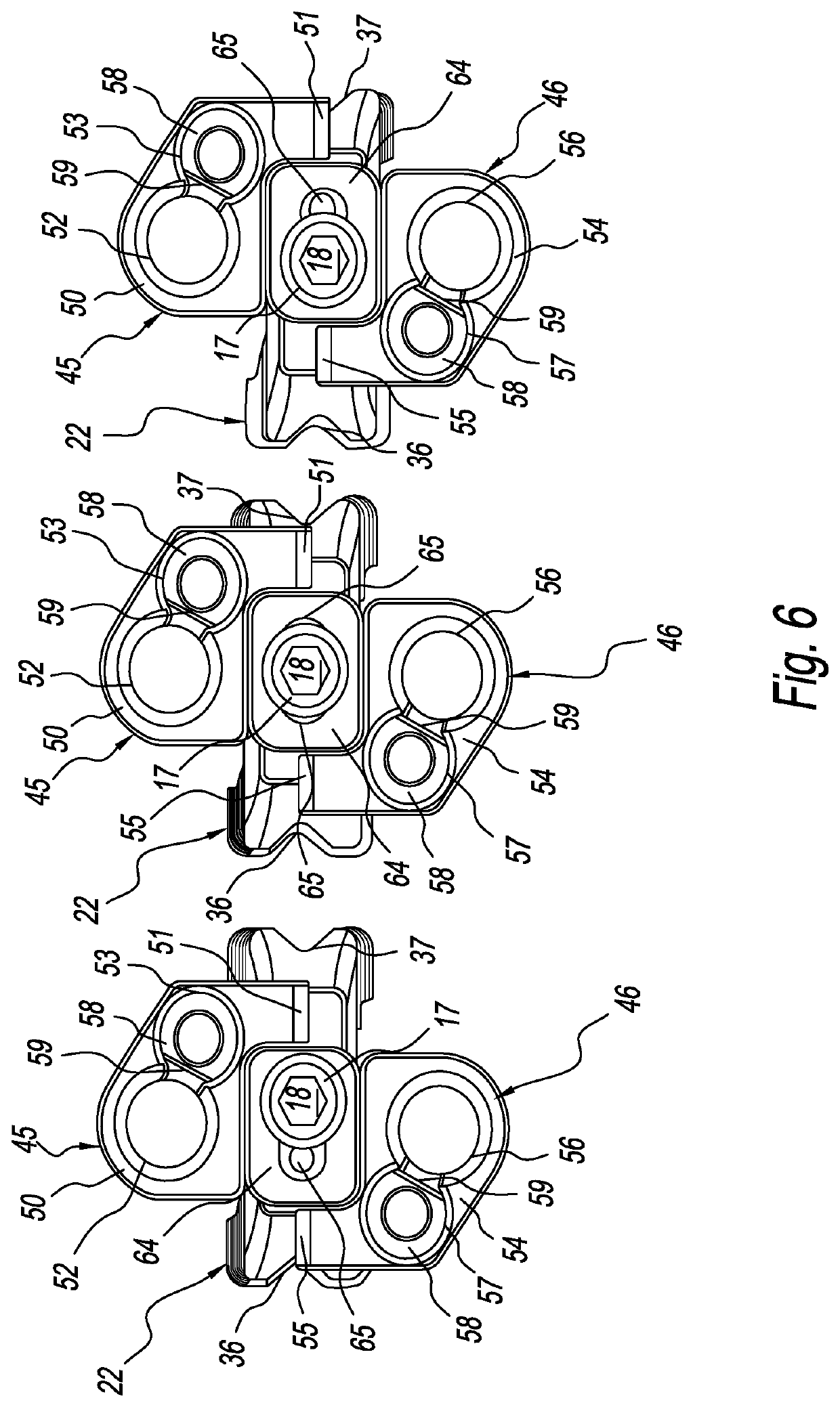
[0038]Referring to FIGS. 1-7, there is depicted an exemplary form of a lateral spine plate, generally designated 14, adapted / configured to be connected, attached, or coupled to a lateral interbody spine cage, generally designated 12, Together, the lateral interbody spine cage 12 and the lateral spine plate 14 is a lateral spinal implant, generally designated 10. The lateral spinal implant 10 is made from a biocompatible material such as, but not limited to, titanium, stainless steel, or an alloy of titanium or steel. Other biocompatible materials may be used and are contemplated. The lateral spine plate implant 10 may be used for any portion of the spine.

[0039]The lateral spine plate 14 may be used generally with all types of lateral interbody spine cages not just with the lateral interbody spine cages shown and / or described herein. The lateral interbody spine cage 14 of the lateral spinal implant 10 is characterized by a generally rectangular body 22 defining a first end or nose 23...


PUM


Abstract

A lateral spine implant has a lateral spine cage and an associated lateral spine plate with one or more folding vertebral attachment arms, each arm configured for attachment to vertebral bone, The ability of the one or more arms to fold allows the lateral spine plate to be inserted / implanted at a lower profile height than traditional lateral spine plates. The lateral spine plate is meant to be used at times of intended or unintended compromise of the anterior longitudinal ligament (ALL) to prevent interbody cage migration, but may be adapted for any lateral plating application. Once expanded, each attachment arm is configured to receive a bone screw for securing the attachment arm to a vertebra, the bone screw retained by rotating cam lock nuts of the attachment arm.

Description

CROSS-REFERENCE TO RELATED APPLICATIONS[0001]This U.S. non-provisional patent application claims the benefit of and / or priority under 35 U.S.C. § 119(e) to U.S. provisional patent application Ser. No. 62 / 487,699 filed Apr. 20, 2017 titled “Lateral Spine Plates With Collapsible Vertebral Attachment Arms,” the entire contents of which is specifically incorporated herein by reference.FIELD OF THE INVENTION[0002]The present invention relates to orthopedic implants such as cages, plates, and screws for the spine and, more particularly to lateral spine cages having vertebral attachment capabilities.BACKGROUND OF THE INVENTION[0003]People contend with spine issues as a result of age, disease, trauma, and congenital and acquired complications and conditions. While some of these issues can be alleviated without surgery, other issues respond better to surgery. In some cases, such as vertebral fusion, surgery includes installing one or more orthopedic implants.[0004]One type of orthopedic impl...

Claims


Application Information

Patent Timeline
Patent Type & Authority Applications(United States)
IPC IPC(8): A61F2/44A61B17/70A61B17/86
CPCA61F2/4455A61B17/70A61F2002/30578A61B17/8605A61B17/7059A61F2002/30433A61F2002/30471A61F2002/305A61B17/8042A61B17/80A61F2/442
Inventor PREDICK, DANIEL P.LAUF, GARRETT D.
Owner LIFE SPINE INC
Why Eureka
Try Eureka