
Method for starting a turbine engine in cold weather and system for starting a turbine engine

a technology for starting a turbine engine and a turbine engine, which is applied in the direction of engine starters, turbine/propulsion engine ignition, machines/engines, etc., can solve the problems of increasing the size of the starting chain, difficulty in circulating lubricant within the turbine engine, and difficulty in starting the turbine engin

Active Publication Date: 2021-03-04
SN DETUDE & DE CONSTR DE MOTEURS DAVIATION S N E C M A
View PDF0 Cites 1 Cited by
  • Summary
  • Abstract
  • Description
  • Claims
  • Application Information

AI Technical Summary

Benefits of technology

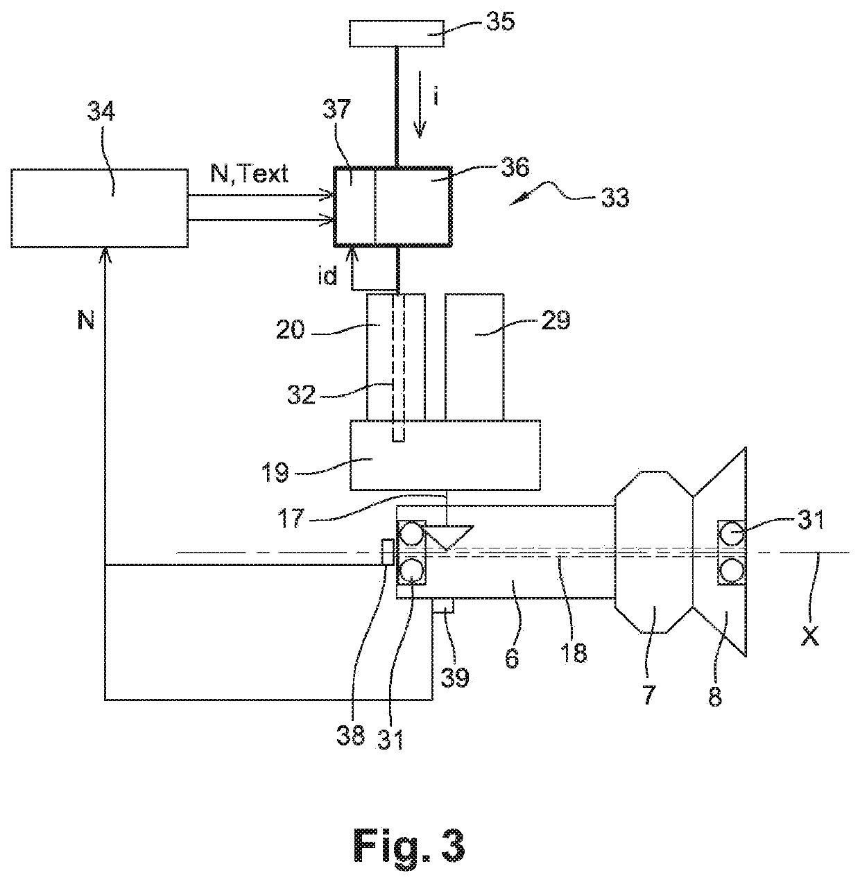
The invention relates to a starting system for a turbine engine that uses an electronic control module to generate signals to control the rotation of the drive shaft in a first direction, then in an opposite direction, and then in a normal direction to start the engine. This system allows for the heating and reduction of viscosity of lubricant in the bearings and rolling elements of the engine, which prevents oversizing of the starting system. The system also includes an accessory gearbox with a lubricant that has a higher viscosity at low temperatures, and the rotation of the drive shaft in one direction can help to heat the lubricant and reduce its viscosity. The invention also includes a method for determining the temperature of the lubricant and the duration of the pre-starting step. The technical effects of the invention include improved starting performance and reduced oversizing of the starting system.

Problems solved by technology

However, in cold weather, i.e. when the outside temperature is typically less than −10° C., and in particular in very cold weather when the outside temperature is typically between −30° C. and −50° C., the turbine engine encounters difficulties at starting, in particular when it has been immobilised for a significant period (more than twenty-four hours, for example).
The lubricant has difficulty in circulating within the turbine engine.
However, this involves an increase in the size of the starting chain (which comprises in particular, the starter but also gears and the drive shaft).
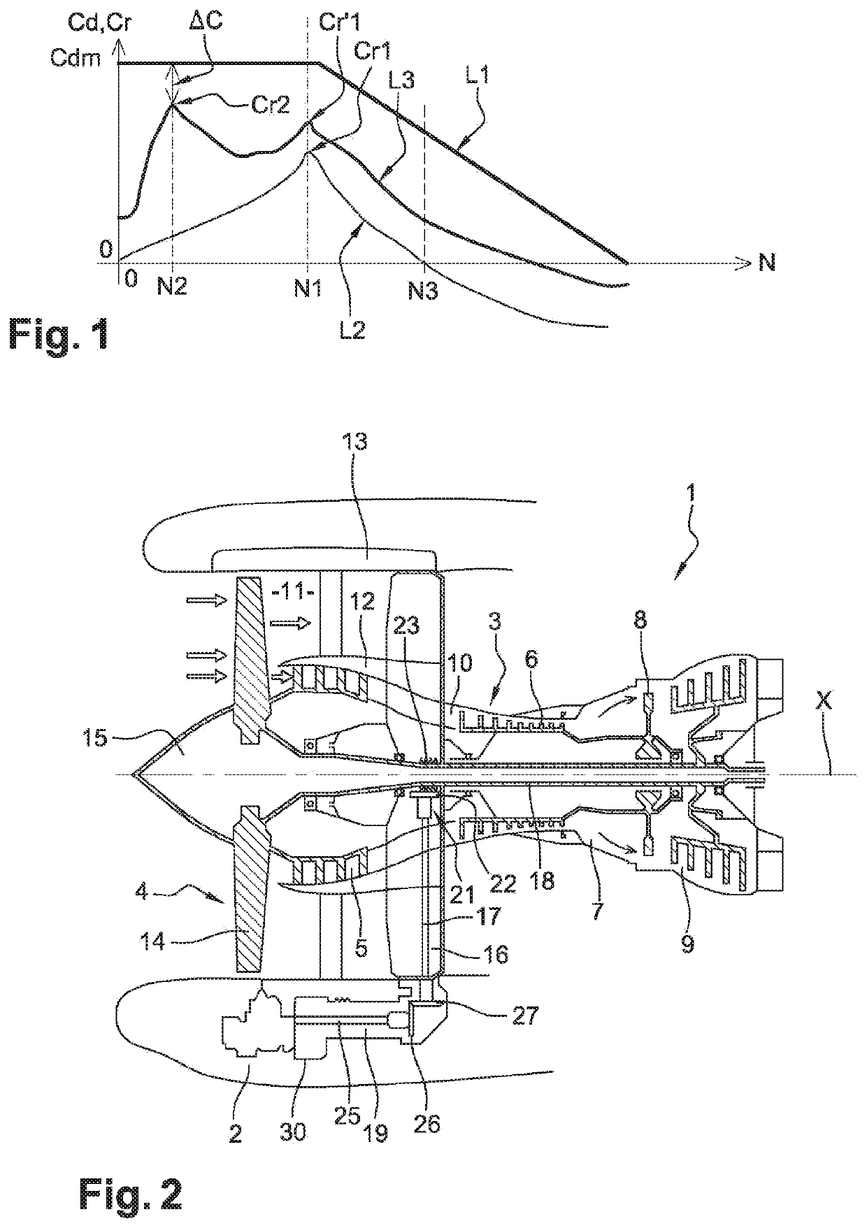
However, this method does not make it possible to prevent resistive torques, in particular the resistive torque Cr2 at low speed.
However, this method also does not make it possible to prevent resistive torques, in particular the resistive torque Cr2 at low speed.
In all of the cases mentioned above, the rotation of the drive shaft in the same direction leads to having to greatly increase the torque applied to carry out both the removal and the heating of the lubricant.
This also results in an increase in fatigue stresses over the entire transmission chain.

Method used


Image

  • Method for starting a turbine engine in cold weather and system for starting a turbine engine
  • Method for starting a turbine engine in cold weather and system for starting a turbine engine

Examples


Embodiment Construction

[0043]FIG. 2 shows an axial, cross-sectional view of a turbine engine of longitudinal axis X, and in particular, a double flow turbine engine according to the invention. Of course, the invention is not limited to this type of turbine engine. This turbine engine 1 generally comprises a nacelle 2 that surrounds a gas generator 3 of longitudinal axis X upstream from which is mounted a fan 3. In the present invention, and in general, the terms “upstream” and “downstream” are defined with respect to the circulation of the gases in the turbine engine 1, and substantially along the longitudinal axis X. The gas generator 3 comprises from upstream to downstream, a low pressure compressor 5, a high pressure compressor 6, a combustion chamber 7, a high pressure turbine 8 and a low pressure turbine 9. The turbine engine 1 comprises a primary duct 10 wherein a primary flow circulates that passes through the gas generator 3. The latter also comprises a secondary duct 11 wherein circulates a secon...


PUM


Abstract

The invention relates to a method for starting a turbine engine in cold weather, including a starting system intended for rotating a drive shaft of the turbine engine, the method comprising the following steps: a pre-starting step in which a first starting signal is generated to control the drive shaft in a first direction of rotation about a longitudinal axis (X) and in a second opposite direction of rotation in an alternating manner; and a starting step in which a second starting signal is transmitted to the starting system in order for the latter to drive the drive shaft of the turbine engine in a normal direction of rotation and in which the drive shaft is rotated until a rotation speed that causes the turbine engine to start.

Description

1. FIELD OF THE INVENTION[0001]The present invention relates to the field of turbine engines, in particular for aircraft. More specifically, the invention relates to a method for starting a turbine engine in cold weather and a system for starting a turbine engine.2. PRIOR ART[0002]The prior art comprises document US-A1-2016-0061061.[0003]A turbine engine generally comprises, from upstream to downstream, according to the circulation of the gases in the turbine engine, a compressor assembly, a combustion chamber and a turbine assembly. The compressor and turbine assembly respectively comprise at least one compressor and at least one turbine. The compressor and the turbine of a body of the compressor and turbine assembly each comprise one or more stages. A drive shaft, typically the shaft of a high pressure body of a two spool and double flow turbine engine, connects a compressor to a turbine to drive the compressor. This drive shaft transmits the power thereof via an accessory gearbox...

Claims


Application Information

Patent Timeline
Patent Type & Authority Applications(United States)
IPC IPC(8): F02C7/275F01D25/10
CPCF02C7/275F01D25/10F05D2210/44F05D2270/303F05D2270/304F05D2220/76F05D2220/323F05D2260/85F05D2270/313Y02T50/60F02C7/26F01D25/36F01D19/02F01D19/00
Inventor DUPAYS, CLEMENTLE PACHE, GWENOLE YANN
Owner SN DETUDE & DE CONSTR DE MOTEURS DAVIATION S N E C M A
Learn More