
Rolling mill with cooling or lubricating device

a technology of cooling or lubricating device and rolling mill, which is applied in the direction of metal rolling stand, metal rolling arrangement, manufacturing tools, etc., can solve the problems of not being able to remount the scrolling of the strip, not being able to mark the nozzle, and not being able to retain the spraying by the bore of the support arm in the rolling mill implemented industrially, so as to improve the cooling of the strip and/or the roll. , to achieve the effect o

Active Publication Date: 2021-03-04
FIVES DMS
View PDF0 Cites 0 Cited by
  • Summary
  • Abstract
  • Description
  • Claims
  • Application Information

AI Technical Summary

Benefits of technology

The present invention proposes a rolling mill with a cooling / lubrication system for the strip or rolls that does not complicate maintenance operations. The system allows for significant fluid flow rates and can be easily integrated into existing rolling mills to improve cooling of the strip and rolls. The invention includes a hollow connector and seat with complementary reliefs that prevent sliding between them when in the first connection position. These technical effects enhance the performance and efficiency of the rolling mill.

Problems solved by technology

In practice and as far as the inventors are aware, this solution of spraying by bores of the support arms does not seem to be retained in rolling mills implemented industrially.
According to the observations of the inventors, the spray nozzles, marked 73 are not able to correctly cool the working rollers because they are located excessively far from the latter, their streams interfering excessively quickly with the lateral support arms, barrels and lateral support rollers and therefore not able to remount the scrolling of the strip.
On the other hand, according to the observations of the inventors, the nozzles marked 72 are not capable of correctly lubricating the contact between the working roller and the intermediate roll because they are located excessively far from the latter.
In use, such rolling mills with insert, have a limited service life for the working roll, due to the poor cooling thereof.
However, this document does not address the problem of the cooling of the working rolls.
However, this improvement is done to the detriment of the supporting of the working roll on one of its sides, by suppressing a lateral support roll and by replacing it with a pad, as the rolling mill is then no longer a reversing mill.
The real difficulty in improving the spraying of the working rolls and of the intermediate rolls in a rolling mill with cassettes is not placing the spray nozzles in the cassette, but knowing how to supply them with lubricating / cooling fluid, and without increasing the duration of maintenance during removal or insertion operations of the cassette in the stand of the rolling mill.
Furthermore, and according to the observations of the inventor, placing the nozzles on the support of the lateral support roll so as to directly spray the working roll is not always possible, in particular when the working roll and the intermediate roll are of small diameter.
However, such a device can be used only to supply with lubricant, either only the bearings of the barrels of the lateral support roll of a support arm, or only for supplying the nozzles of a support arm with fluid.
This trajectory of the fluid, complex, from the chock to the support arm, through the hollow shaft, generates load losses, limiting the flow rates.
According to the observations of the inventors, this lubrication is insufficient, in particular for the rolls placed under the strip.
Furthermore, and when the speed of the rolling mill becomes substantial, the centrifugal force at the circumference of the intermediate roll tends to spin the roll in such a way that little cooling fluid reaches the working roll.
These slidings are detrimental to the seal of the connection and are at the origin of cooling fluid leaks, and further,such a solution according to document WO 2015 / 011373 is very often provided native to the rolling mill, but becomes expensive when it entails improving the cooling of an existing rolling mill, in particular in that it requires reworking the load spreading beam and the means for applying a preload.

Method used


Image

  • Rolling mill with cooling or lubricating device
  • Rolling mill with cooling or lubricating device
  • Rolling mill with cooling or lubricating device

Examples


Embodiment Construction

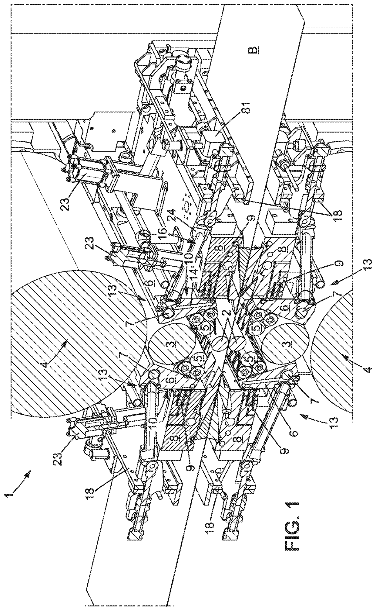
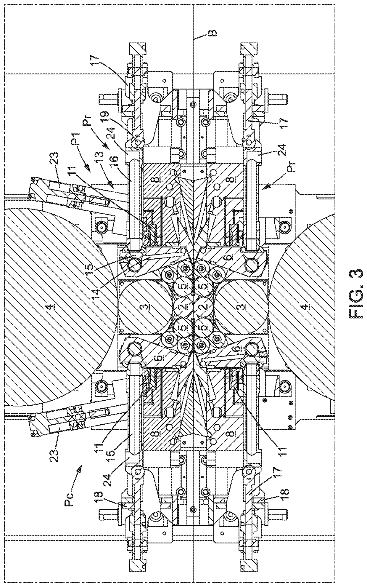
[0096]Thus the invention relates first of all to a rolling mill 1 comprising:[0097]a stand 30 comprising two pairs of uprights 31 separated between them at the two ends of the stand, at least two uprights of the same pair defining an access window,[0098]two working rolls 2, able to surround a strip to be rolled, two support rolls 4, and two intermediate rolls 3, the support rolls 4 and the intermediate rolls 3, being rotatably mounted at the ends thereof on chocks,[0099]lateral support rolls 5, able to support the working rolls 2 laterally, each lateral support roll being borne by a support arm 6, mounted with the ability to pivot on an axis 7,[0100]load spreading beams 8 extending between the corresponding uprights of each pair, and means 9 for applying a preload on each support arm 6, intended for engaging with one of the support arms at a support surface 10, and comprising at least one preload actuating cylinder 11 integral with one of the load spreading beams 8,[0101]one or more...


PUM

PropertyMeasurementUnit
distanceaaaaaaaaaa
displacementaaaaaaaaaa
thicknessaaaaaaaaaa

Abstract

Disclosed is a rolling mill including: a stand; two working rolls, two support rolls, and two intermediate rolls; lateral support rolls, able to support the working rolls laterally, each lateral support roll being borne by a support arm, mounted with the ability to pivot; load spreading beams and a mechanism for applying a preload on each support arm, including at least one preload actuating cylinder; one or more spray nozzles for a lubricating / cooling fluid, and wherein at least one of the nozzles, is carried on one of the support arms and in which the fluid supply circuit for the at least one nozzle comprises a device for connection / disconnection with the support arm with actuator. The actuator is an actuator distinct from the actuating cylinder of the mechanism for applying a preload.

Description

[0001]This application is the U.S. national phase of International Application No. PCT / FR2019 / 050148 filed Jan. 23, 2018 which designated the U.S. and claims priority to FR 18 50594 filed Jan. 25, 2018, the entire contents of each of which are hereby incorporated by reference.BACKGROUND OF THE INVENTIONField of the Invention[0002]The invention relates to a rolling mill, and more particularly relates to the aspect of the cooling and / or the lubrication of the rolls of such a rolling mill.[0003]The field of the invention is more particularly that of laterally supported Sexto stand rolling mills, and in particular rolling mills known under the name “Z High”.[0004]These rolling mills have application, in line, for example, in annealing and pickling lines or, off line, as reversing mills, for metal strips.Description of the Related Art[0005]A Quarto stand rolling mill comprises a stand wherein four rolls with parallel axes are provided, namely respectively two working rolls, lower and upp...

Claims


Application Information

Patent Timeline
Patent Type & Authority Applications(United States)
IPC IPC(8): B21B45/02B21B13/02
CPCB21B45/0251B21B45/0233B21B13/02B21B13/145B21B13/147B21B27/10
Inventor ERNST DE LA GRAETE, CONRAD
Owner FIVES DMS
Learn More