
Decentralized cyber-physical system

a cyberphysical system and cyberphysical technology, applied in the field of cyberphysical systems, can solve the problems of significant increase in system complexity, time-consuming and performed processes, and difficulty in maintaining stability under all operating conditions, and achieve the effects of reducing downtime, fast fault recovery solution, and fault tolerance and flexibility

Active Publication Date: 2021-02-18
DELTA ELECTRONICS INTL SINGAPORE
View PDF0 Cites 1 Cited by
  • Summary
  • Abstract
  • Description
  • Claims
  • Application Information

AI Technical Summary

Benefits of technology

This patent describes a system that can detect and alert about malfunctions in components of a cyber-physical system. The system is designed to be flexible and scalable, with a resilience manager that uses Non-Functional Properties (NFP) of components to reduce misjudgments and prevent operational issues. The system also optimizes the deployment of components to avoid time-consuming operations in large-scale systems. Overall, the invention helps to maintain the system's resilience and reliability, reducing downtime and improving overall performance.

Problems solved by technology

With the growing scale of CPS implemented in industrial production line, it is challenging to maintain stability under all operating conditions.
How to reduce the downtime and increase the resiliency to faults become a crucial issue in system design.
Besides, the rapid evolution of CPS has led to a significant increase in system complexity.
This further introduces new challenges in satisfying all the system requirements during the design and execution.
This process is time consuming and performed over a long period of time, even months.
However, manufacturers are now facing ever-shorter product life cycles.
In other words, since the troubleshooting method has to be adjusted regularly or frequently, it cannot meet the rapidly changing needs of the product and the production line.
Unfortunately, for a large-scale CPS with numerous components, the source of the faults cannot be identified whenever the system violates the centralized contract.
However, while the decentralized manner is used to monitor, it makes the CPS sensitive to disturbance.
Consequently, one false alarm can impact the entire process of the CPS.
On the other hand, how to decompose the root contract and refine the sub-contracts is also a problem to be solved.
If the root contract is decomposed and the sub-contract is optimized manually, it causes time-consuming and other problems due to the numerous components.

Method used


Image

  • Decentralized cyber-physical system
  • Decentralized cyber-physical system
  • Decentralized cyber-physical system

Examples


first embodiment

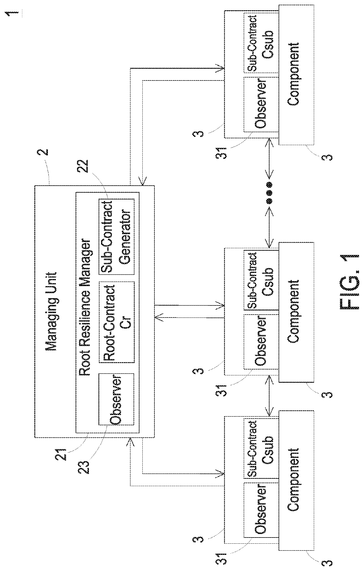
[0023]Please refer to FIG. 1. FIG. 1 shows a framework structure of a decentralized cyber-physical system according to the present invention. In the embodiment, the cyber-physical system 1 (hereinafter referred to as CPS 1) includes a managing unit 2 and a plurality of components 3 to be monitored. The managing unit 2 is connected to the plurality of components 3 through a communication network for monitoring the operations of the components 3 and the overall operations of the CPS 1. The managing unit 2 may be connected to the plurality of components 3 wirelessly or by wire. The managing unit 2 includes a root resilience manager 21. The root resilience manager 21 is configured to monitor at least one non-functional properties (NFP) of the CPS 1. Namely, the NFP, such as the actual operating time and / or the actual energy with respect to the actual voltage and / or the actual current, are monitored in each component 3 by the root resilience manager 21. The root resilience manager 21 inc...

second embodiment

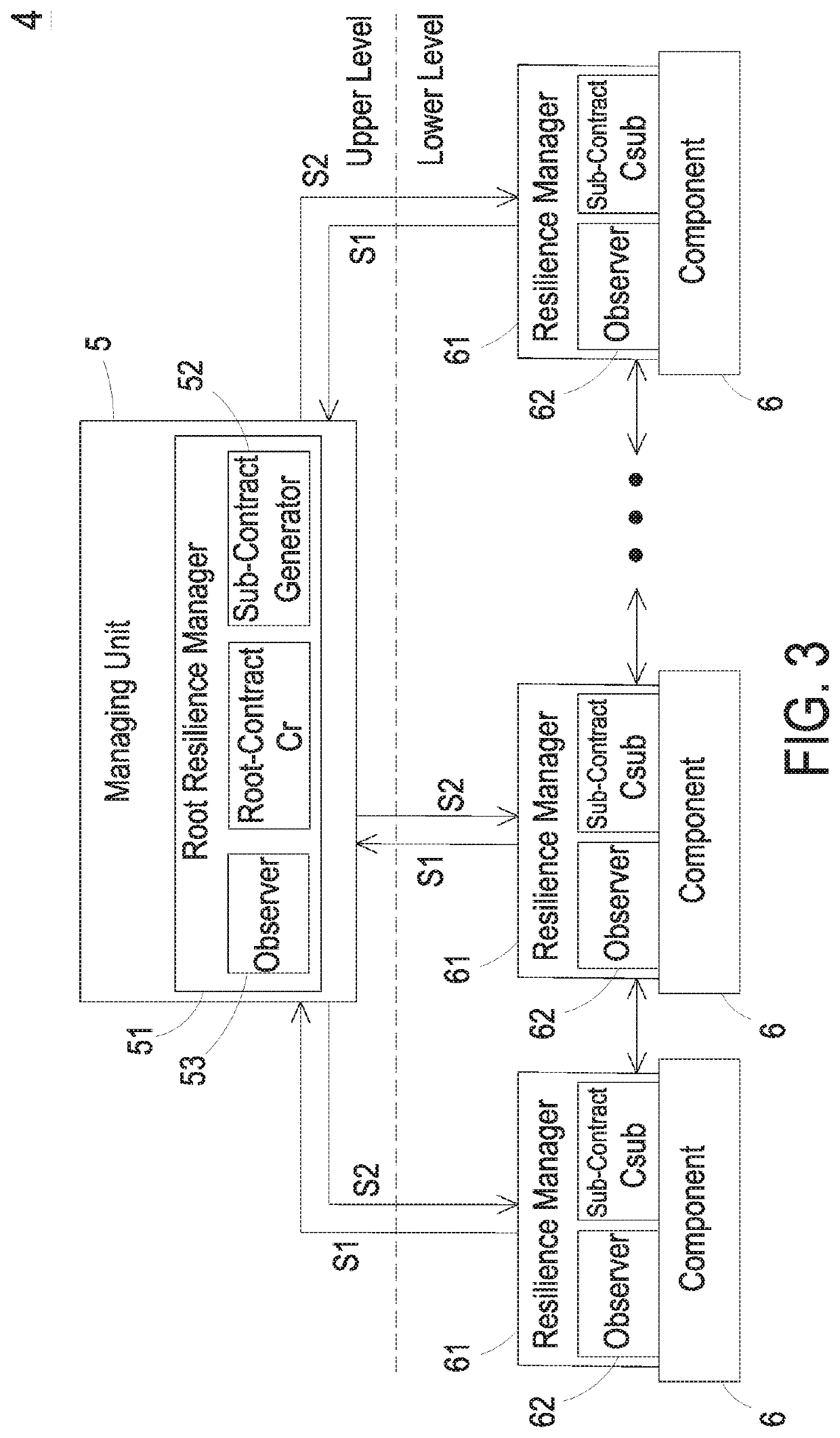
[0031]Please refer to FIG. 3. FIG. 3 shows a structure of a decentralized cyber-physical system according to the present invention. In the embodiment, the decentralized cyber-physical system 4 (hereafter referred to as CPS 4) includes a managing unit 5 and a plurality of components 6 to be monitored. In the embodiment, the managing unit 5 and the plurality of components 6 are located at the physical space. The managing unit 5 is connected to the plurality of components 6 through a communication network for monitoring the operations of the components 6 and the overall operations of the CPS 4. The managing unit 5 includes a root resilience manager 51. Each of the plurality of components 6 includes a resilient manager 61. In the embodiment, the root resilient manager 51 and the plurality of resilient managers 61 are configured to form a resilience management framework divided into at least two levels. The root resilient manager 51 is disposed in a logical upper level (or nonleaf-level ...

third embodiment

[0035]Based on the root-contract Cr and the sub-contracts Csub, the foregoing resilience management hierarchy is designed to have at least two levels, called as two-level hierarchy system. In other embodiment, a plurality of two-level hierarchy systems are used to form a multiple-level hierarchy system for a large-scale CPS. FIG. 4 shows a framework structure of a decentralized cyber-physical system according to the present invention. In the embodiment, the cyber-physical system 7 (hereinafter referred to as CPS 7) is configured to form a multiple-level hierarchy system. The cyber-physical system 7 includes at least one sub-system 4a, which is a two-level sub-system. In the embodiment, the sub-system 4a has the similar structures, elements, and functions as those of the foregoing embodiment in FIG. 3, and includes a managing unit 5a and a plurality of component 6a. The managing unit 5a and the component 6a also have the similar structures, elements, and functions as the managing uni...


PUM


Abstract

The disclosure relates to a decentralized cyber-physical system including a managing unit and a plurality of components. The managing unit includes a root resilient manager including a root contract and a sub-contract generator. The sub-contract generator is configured to decompose the root contract into a plurality of sub-contracts and assign the plurality of sub-contracts to the plurality of components, respectively. Each component includes at least one observer configured to monitor if the property of the individual component violates the sub-contracts corresponding thereto. When one of the plurality of sub-contracts violates during the runtime of the decentralized cyber-physical system, the root resilience manager issues an alarm.

Description

CROSS-REFERENCE TO RELATED APPLICATION[0001]This application claims the priority of India Provisional Patent Application No. 201921033059 filed on Aug. 16, 2019, entitled “DECENTRALIZED MONITORING FRAMEWORK FOR CYBER-PHYSICAL SYSTEMS”. The entire contents of the above-mentioned patent application are incorporated herein by reference for all purposes.FIELD OF THE INVENTION[0002]The present invention relates to a cyber-physical system, and more particularly to a decentralized cyber-physical system with a resilience manager in a monitoring framework.BACKGROUND OF THE INVENTION[0003]Cyber-physical system (CPS) is a key technology of “Industry 4.0” and is currently a hot topic. By utilizing computers and sensors and linking various devices, machines and digital systems through a new generation of network technology, the communication and interaction between each other are achieved, so that the cyber components and the physical components are intertwined as a smart system.[0004]With the g...

Claims


Application Information

Patent Timeline
Patent Type & Authority Applications(United States)
IPC IPC(8): G06F11/07
CPCG06F11/0757G06F11/0709G05B19/4184G05B19/41845G06F11/3006G06F11/3013G06F11/3058G06F11/3065G06F11/3089G05B2219/32181G05B23/0205G05B23/0254
Inventor XU, ZHIHENGNG, JUN XIAN DANIELBATAINEH, OMAREASWARAN, ARVINDANDALAM, SIDHARTASOON, BO WOON JEFFREY
Owner DELTA ELECTRONICS INTL SINGAPORE
Learn More