
Image forming apparatus having image carrier and belt member

a technology of image forming apparatus and belt member, which is applied in the direction of electrographic process apparatus, instruments, optics, etc., can solve the problems of increasing the number of mechanical components, increasing the cost, and the waiting time during image formation cannot be shortened, so as to reduce the downtime and prevent the generation of friction

Inactive Publication Date: 2015-12-15
CANON KK
View PDF8 Cites 0 Cited by
  • Summary
  • Abstract
  • Description
  • Claims
  • Application Information

AI Technical Summary

Benefits of technology

The present invention is about an image forming apparatus that can reduce downtime while avoiding friction between the image carrier and the belt member when replacing them. The technical effect of the invention is that it reduces the time it takes to fix issues with the image carrier or belt member, which can help to increase efficiency and prevent damage to the equipment.

Problems solved by technology

When the intermediate transfer belt unit or the photosensitive drum is replaced with the intermediate transfer belt unit and the photosensitive drum being kept in abutment with each other, friction may be generated between the intermediate transfer belt unit and the photosensitive drum, causing deterioration thereof due to wear or the like.
According to the above prior arts, however, there may be cases where the intermediate transfer belt or the photosensitive drums is replaced without separating the intermediate transfer belt and the photosensitive drum from each other due to an operation error, a mistake, or the like, causing deterioration thereof due to friction.
Moreover, manually separating the intermediate transfer belt and the photosensitive drum from each other will increase the number of mechanical components, resulting in cost increase.
With this arrangement, however, whenever image formation is started, the intermediate transfer belt and the photosensitive drum are brought into abutment with each other, and hence waiting time during image formation cannot be shortened, and the start of image formation is late.
Namely, there is downtime due to abutment each time, resulting in poor merchantability.

Method used


Image

  • Image forming apparatus having image carrier and belt member
  • Image forming apparatus having image carrier and belt member
  • Image forming apparatus having image carrier and belt member

Examples


Embodiment Construction

[0024]The present invention will now be described with reference to the drawings showing an embodiment thereof.

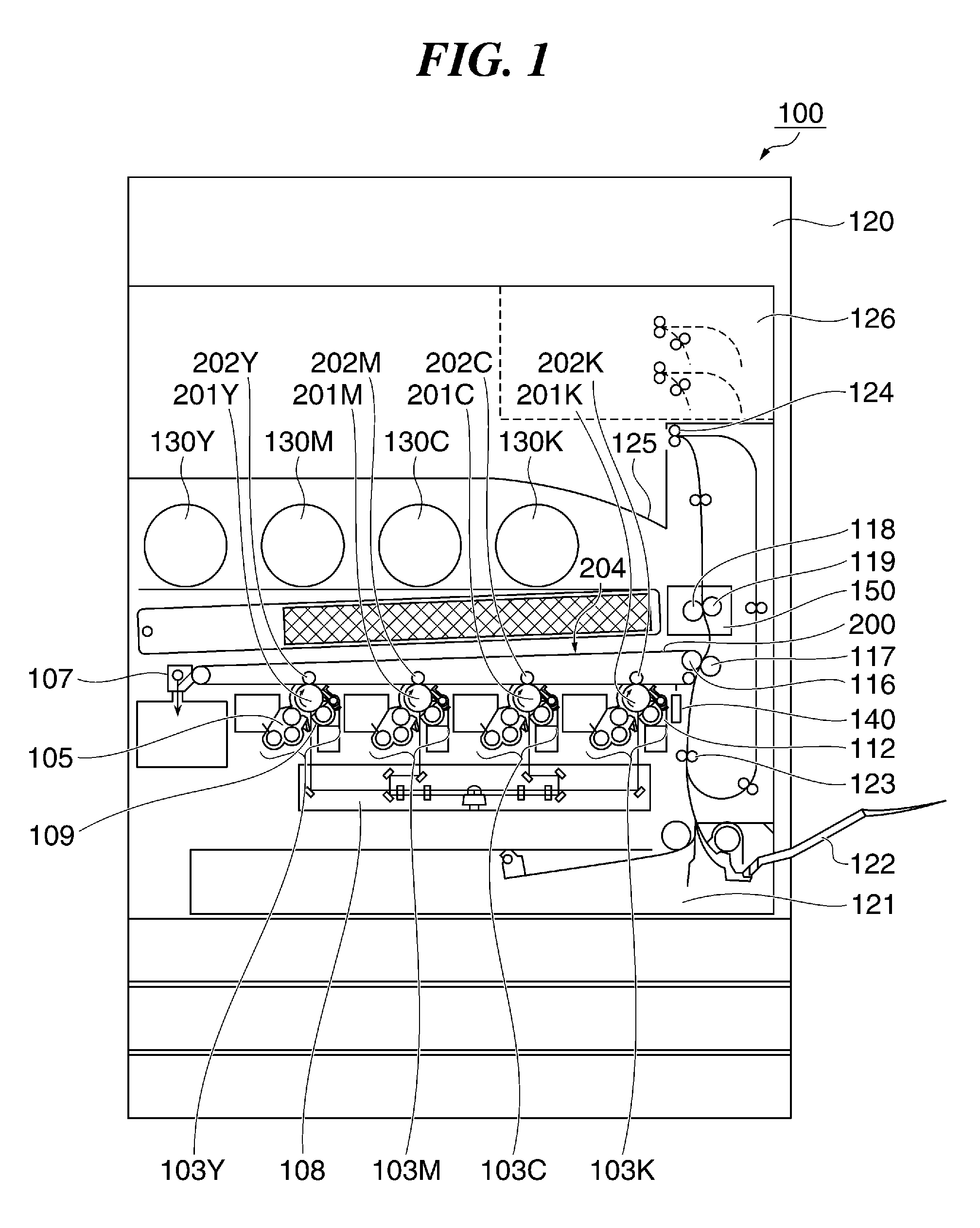
[0025]FIG. 1 is a cross-sectional view schematically showing an arrangement of an image forming apparatus according to the embodiment of the present invention.

[0026]As an example of this image forming apparatus 100, a multi-color or full-color electrophotographic image forming apparatus integrated with a developer containing device to which a developer container containing developers (hereafter referred to as “toners”) replenishing a developing device is attachable is illustrated. In particular, the image forming apparatus 100 is an inline-type image forming apparatus in which a plurality of process cartridges is arranged in a line.

[0027]Specifically, the image forming apparatus 100 has removable process cartridges 103 (103Y, 103M, 103C, and 103K) arranged at regular intervals in a substantially horizontal straight line. The process cartridges 103Y, 103M, 103C, and 103K for...


PUM


Abstract

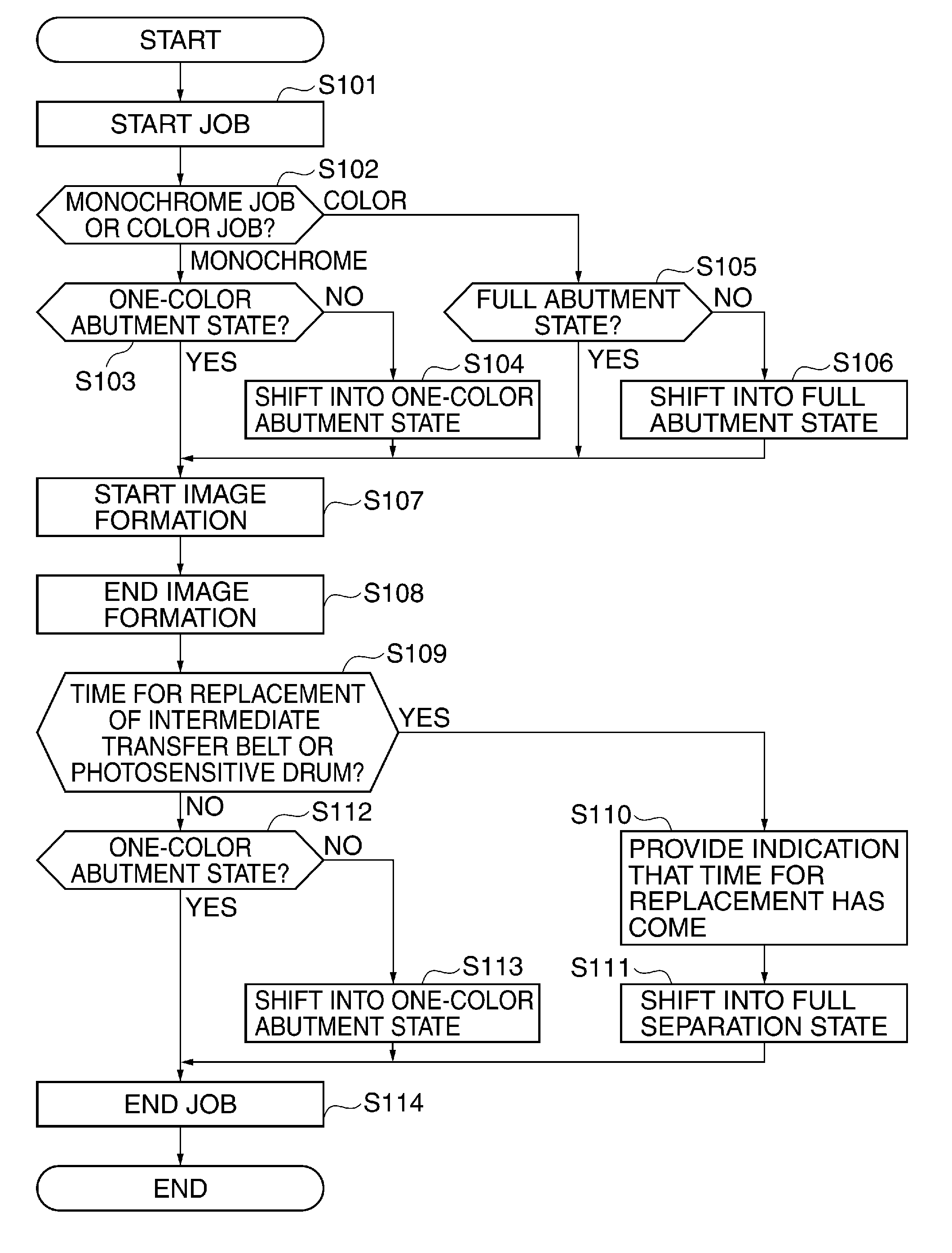
An image forming apparatus which is capable of reducing downtime while preventing generation of friction between an image carrier and a belt member when the image carrier or the belt member is replaced. Whether or not a photosensitive drum should be replaced is determined based on usage conditions of the photosensitive drum, and when it is determined that the photosensitive drum should be replaced, a separating operation of separating an intermediate transfer belt from the photosensitive drum is carried out after an image formed on the intermediate transfer belt is transferred to a recording medium. When it is not determined that the photosensitive drum should be replaced, the separating operation is not carried out after the image formed on the intermediate transfer belt is transferred to the recording medium.

Description

BACKGROUND OF THE INVENTION[0001]1. Field of the Invention[0002]The present invention relates to an image forming apparatus in which a toner image carried on an image carrier is transferred to a belt member, and in particular to an image forming apparatus whose image carrier or belt member is replaceable.[0003]2. Description of the Related Art[0004]Conventionally, image forming apparatuses having a photosensitive drum (image carrier) bearing a toner image, a transfer roller, and an intermediate transfer belt (belt member) have been known. At the time of image formation, the transfer roller is brought into an abutment state in which it is pressed against the photosensitive drum via the intermediate transfer belt, and a toner image formed on the photosensitive drum is transferred to the intermediate transfer belt. Some of those image forming apparatuses are configured such that the photosensitive drum or a unit including the same and the intermediate transfer belt or a unit including ...

Claims


Application Information

Patent Timeline
Patent Type & Authority Patents(United States)
IPC IPC(8): G03G15/08G03G15/01G03G15/00
CPCG03G15/0136G03G15/553G03G15/751
Inventor SUZUKI, SHINYA
Owner CANON KK
Learn More