
Eye tracking fixation monitoring systems and methods

a technology of fixation monitoring and eye tracking, applied in the field of eye tracking system and method, can solve problems such as inability to properly function, system may not be able to properly function, and inaccurate readings

Active Publication Date: 2021-02-18
ALCON INC
View PDF9 Cites 1 Cited by
  • Summary
  • Abstract
  • Description
  • Claims
  • Application Information

AI Technical Summary

Benefits of technology

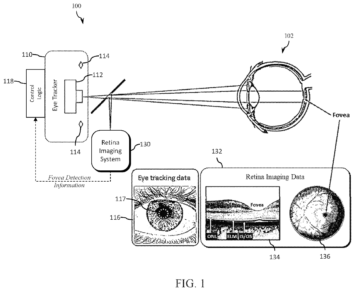
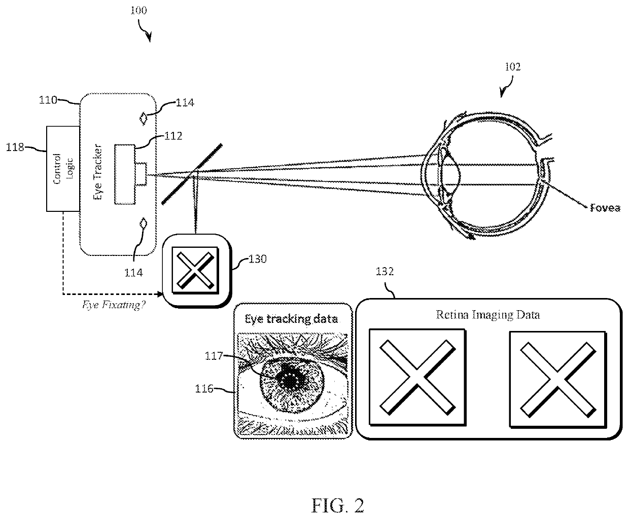
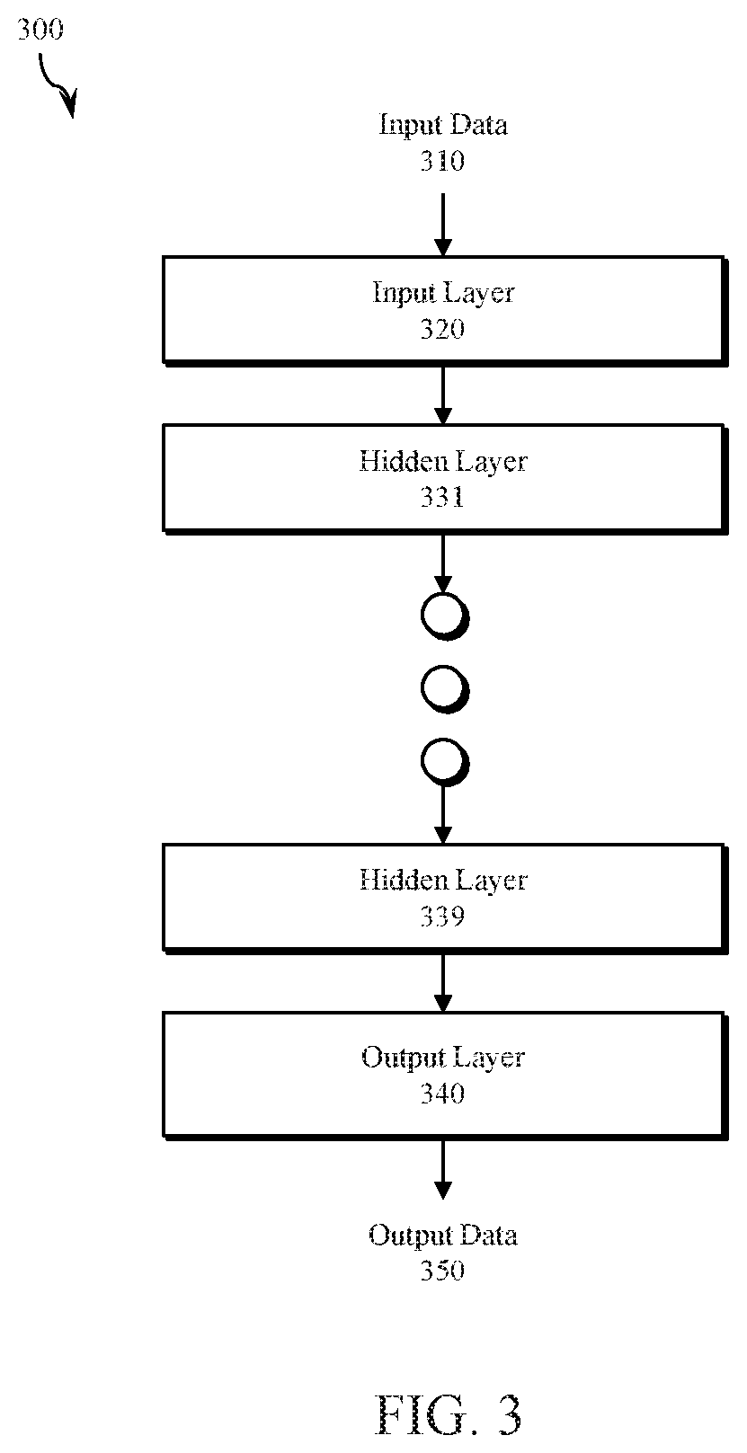
The patent describes a system and method for evaluating and facilitating eye fixation in eye imaging, tracking, and surgical procedures. The system uses a retina imaging system and an eye tracker to capture images of the eye and track its position and orientation. The system analyzes the images to determine the eye's fixation position and orientation relative to a reference position and orientation. This allows the system to detect if the eye is properly fixated and adjust the position and orientation of the eye during the procedure. The system can also use neural networks to analyze the eye tracking data and improve the accuracy of the eye fixation parameters. Overall, the system improves the accuracy and efficiency of eye fixation in various eye imaging and surgical procedures.

Problems solved by technology

If the patient isn't properly fixating, readings may be inaccurate and / or the system may not be able to properly function.
However, existing approaches have many drawbacks including human error in the patient's attempt to fixate (e.g., an elderly patient may be unable to maintain eye position, a patient may lack sufficient concentration to fixate the eye, the patient may not look directly at the target object, etc.) and human error by the operator monitoring the patient during the procedure.
In another approach, retina scanning and imaging analysis may be used to track the patient's eye position and orientation, but operation of a retinal imaging system can interfere with a diagnostic procedure.
As a result, retina scanning and imaging systems are often shut down or otherwise rendered inoperable for use in eye tracking during a diagnostic procedure performed using the ophthalmic device.

Method used


Image

  • Eye tracking fixation monitoring systems and methods
  • Eye tracking fixation monitoring systems and methods
  • Eye tracking fixation monitoring systems and methods

Examples


Embodiment Construction

[0034]Systems and methods are disclosed herein for evaluating and / or facilitating eye fixation in an eye imaging, tracking, diagnostic and / or surgical system. For example, the improvements disclosed herein may be used to assist a device operator in aligning the patient's line-of-sight to an optical axis of an ophthalmic device prior to activating an ophthalmic device to perform a measurement sequence or other diagnostic procedure.

[0035]In accordance with various embodiments, accurate measurement of a patient's eye is facilitated using a diagnostic system that determines whether the patient's line-of-sight (also referred to herein as the patient's visual axis) is in alignment with an optical axis of the diagnostic system. The patient's line-of-sight / visual axis may be the axis along which the patient's eye is oriented to look at an object. The diagnostic data acquired in accordance with the systems and methods disclosed herein is more meaningful and accurate than data acquired throug...


PUM


Abstract

Systems and methods for tracking eye movement during a diagnostic procedure include a retina imaging system configured to capture a first plurality of images of an eye and detect a presence of a fovea, an eye tracker configured to capture a second plurality of images of the eye and track a position and orientation of the eye; and a control processor configured to synchronize the first and second plurality of images, determine a time at which the fovea is detected in the first plurality of images, and determine one or more images from the second plurality of images to be classified as representative of fixation. The classified images are analyzed to determine eye fixation status during the diagnostic procedure based on eye tracking data.

Description

BACKGROUNDField of the Disclosure[0001]The present disclosure relates generally to eye tracking systems and methods, and more particularly, for example, to systems and methods for tracking the position and / or orientation of an eye in imaging, tracking, diagnostic and / or surgical systems.Description of Related Art[0002]A wide variety of ophthalmic devices are used to image, measure, diagnose, track, surgically correct and / or surgically repair a patient's eyes. The operation of an ophthalmic device such as a topography device, a keratometry device, a wavefront analyzer or another device that measures aspects of the eye (e.g., optically, geometrically, etc.), is often based on the assumption that the eye is maintained in a defined position and orientation with respect to the diagnostic device. The patient may be positioned by a human operator of the ophthalmic device and instructed, for example, to look into the device at a target object (e.g., a fixation light) to align the patient's ...

Claims


Application Information

Patent Timeline
Patent Type & Authority Applications(United States)
IPC IPC(8): A61B3/113G06K9/00G06T7/73A61B3/12A61B3/10A61B3/14A61B3/00A61B3/18
CPCA61B3/113G06K9/00604G06T7/74A61B3/1225A61B3/102G06T2207/30041A61B3/0025A61B3/18G06K2209/05G06T2207/10101A61B3/14A61B5/0066A61B5/7267A61B3/12A61B3/152G06V40/19G06V2201/03
Inventor BIRKNER, SASCHAGRÜNDIG, MARTIN
Owner ALCON INC
Learn More