
Method for non-invasive determination of the flow or the flow rate in an electrically conductive object through which a gaseous medium flows, and acoustic flow meter for carrying out the method

a technology of electrically conductive objects and flow rates, which is applied in the field of non-invasive determination of flow or flow rate in electrically conductive objects, to achieve the effect of improving measurement or determination, and improving measurement or determination of flow

Active Publication Date: 2021-01-21
ROSEN SWISS
View PDF0 Cites 1 Cited by
  • Summary
  • Abstract
  • Description
  • Claims
  • Application Information

AI Technical Summary

Benefits of technology

The patent describes a way to improve the detection and evaluation of signals from a small sensor. This is done by using a special approach that reduces interference from reflections at contact points on the sensor. This allows for a better determination of the flow or flow rate of a gas. Additionally, the design of the invention ensures a minimal contact area with the object, which further reduces interference. This results in a more accurate and reliable flow measurement.

Problems solved by technology

Moreover, the main beam of the ultrasonic wave is guided past the receiving transducer and is thus not directly detected.

Method used


Image

  • Method for non-invasive determination of the flow or the flow rate in an electrically conductive object through which a gaseous medium flows, and acoustic flow meter for carrying out the method
  • Method for non-invasive determination of the flow or the flow rate in an electrically conductive object through which a gaseous medium flows, and acoustic flow meter for carrying out the method
  • Method for non-invasive determination of the flow or the flow rate in an electrically conductive object through which a gaseous medium flows, and acoustic flow meter for carrying out the method

Examples


Embodiment Construction

[0051]Identically or similarly acting parts are provided—if appropriate—with identical reference signs. Individual technical features of the exemplary embodiments described hereinafter can also result in refinements according to the invention with the features of the above-described exemplary embodiments.

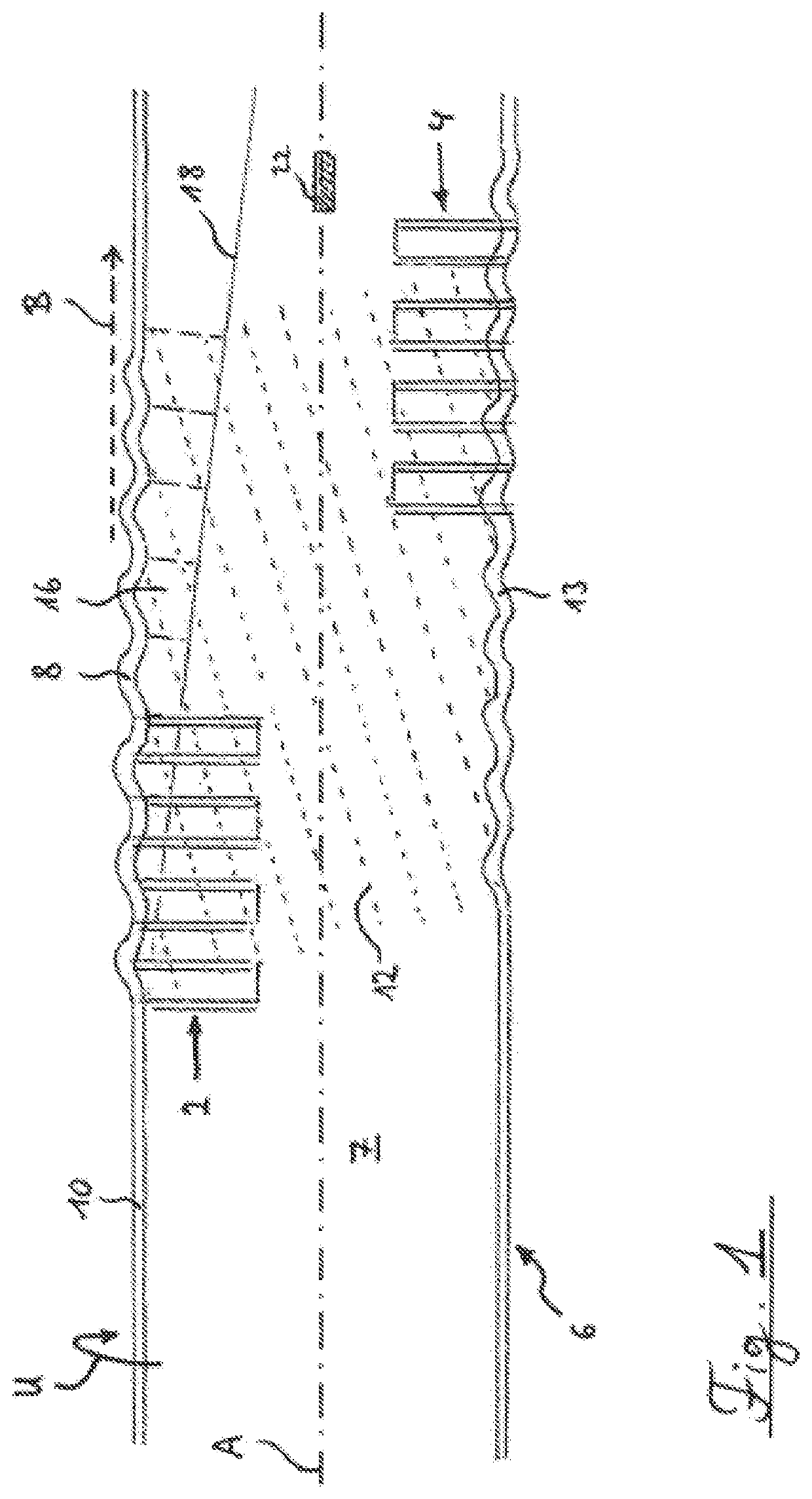
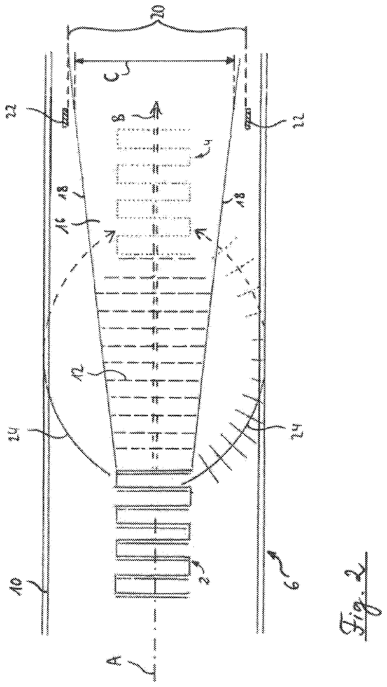
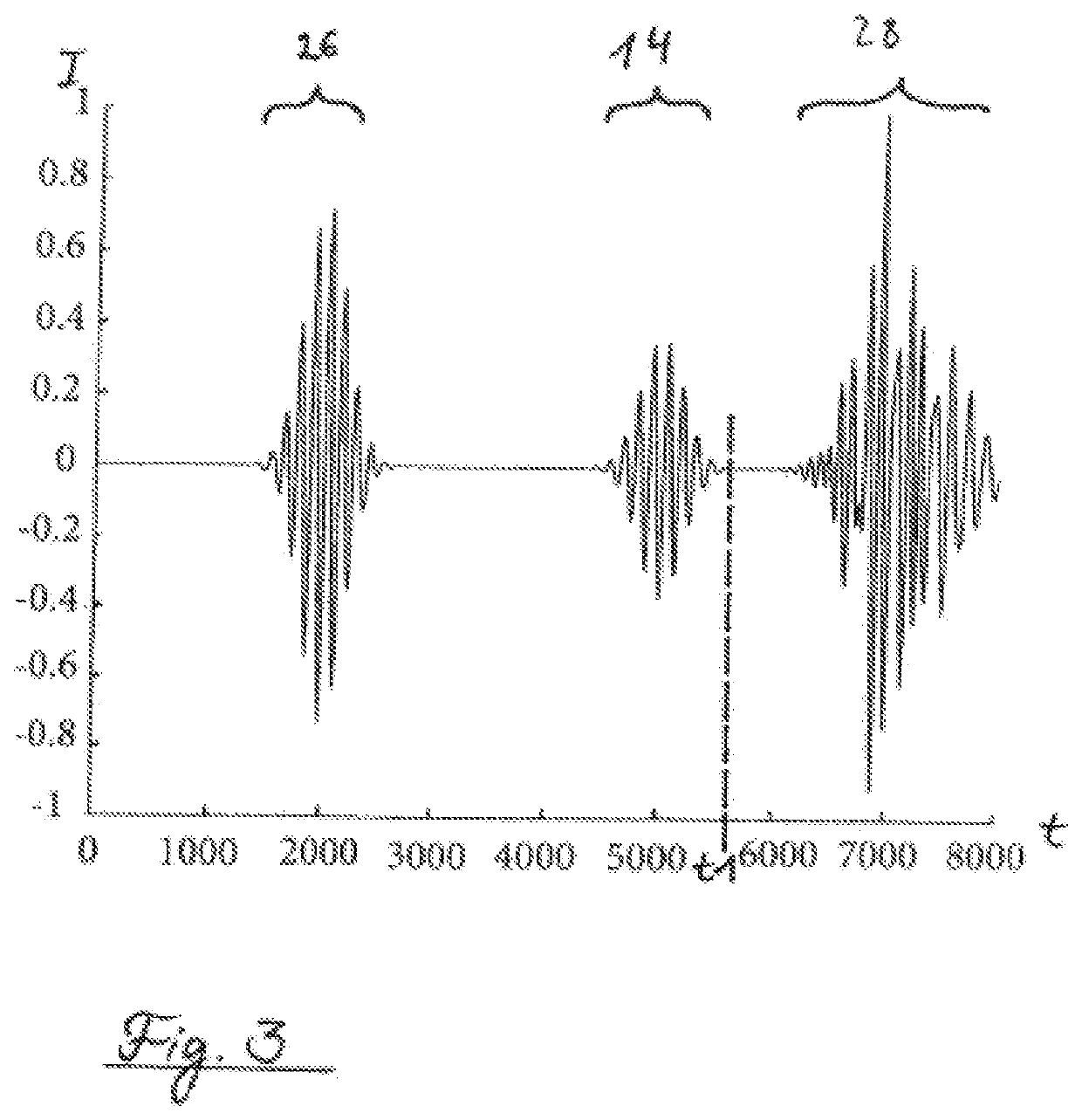
[0052]An acoustic flow meter according to the invention is (partially) shown in FIGS. 1 and 2, having a first conductor arrangement 2 functioning as an emitting transducer and a second conductor arrangement 4 functioning as a receiving transducer, which are arranged externally on a tubular object 6, the longitudinal axis of which is identified by A and through which a gaseous medium 7 flows. The first conductor arrangement 2 and the second conductor arrangement 4 are spaced apart in the longitudinal direction of the object 6. The first conductor arrangement 2 functioning as an emitting transducer generates an ultrasonic wave 8, formed in particular as a Lamb wave, in the object wall...


PUM


Abstract

A method for noninvasive determination of the flow or the flow rate in an electrically conductive object, through which a gaseous medium flows, by means of an acoustic flow meter, wherein an emitting transducer is arranged on the object wall- and a receiving transducer is arranged spaced apart in the longitudinal direction of the object on the object wall, an ultrasonic wave is generated in the object by means of the emitting transducer, which is partially coupled as a longitudinal wave into the medium, and a useful signal, which at least partially results due to the longitudinal wave, is detected by the receiving transducer, wherein the flow rate is determined from the useful signal via an evaluation device, wherein the emitting transducer is arranged in a first position in the circumferential direction around a longitudinal axis of the object and the receiving transducer is arranged in a second position, varied in relation to the first position around the longitudinal axis, outside the main beam of the ultrasonic wave, and the width of the main beam is restricted to a sector between two contact points of a sensor mechanism.

Description

BACKGROUND[0001]The present invention relates to a method for noninvasive determination of the flow or the flow rate in an electrically conductive object through which a gaseous medium flows, in particular in a pipe or a pipeline, by means of an acoustic flow meter.[0002]In conventional, noninvasive, acoustic flow meters, an ultrasonic wave, formed in particular as a Lamb wave, which is partially coupled as a longitudinal wave into the medium, is generated in the object by an emitting transducer arranged on or close to the object wall. A useful signal, which at least partially results due to the longitudinal wave, is detected by a receiving transducer spaced apart in the longitudinal direction of the object from the emitting transducer and arranged on or close to the object wall. The flow or the flow rate of the medium is determined from the useful signal via an evaluation device.[0003]With gaseous media, such measurements are problematic since due to the poor acoustic coupling betw...

Claims


Application Information

Patent Timeline
IPC IPC(8): G01F1/66
CPCG01F1/662G01F1/667G01N29/024G01F1/668
Inventor BRÜCHER, MARTINBAUERNSCHMITT, RÜDIGERRODRIGUEZ, NATALIA
Owner ROSEN SWISS
Learn More