
Work supporting and rotating apparatus

a technology for supporting and rotating equipment, which is applied in the direction of work benches, soldering auxiliaries, large fixed members, etc., can solve the problems of difficult and anti-economical to move the positioners to another work area within the same factory, difficult and anti-economic to move the positioners to another work area, and difficult to achieve the positioning and perfect alignment of circular sections involving the use of conventional systems. , to achieve the effect of convenient transportation to the worksite and easy installation at the worksi

Pending Publication Date: 2021-01-21
DALMAC ENTERPRISES PTY LTD
View PDF10 Cites 10 Cited by
  • Summary
  • Abstract
  • Description
  • Claims
  • Application Information

AI Technical Summary

Benefits of technology

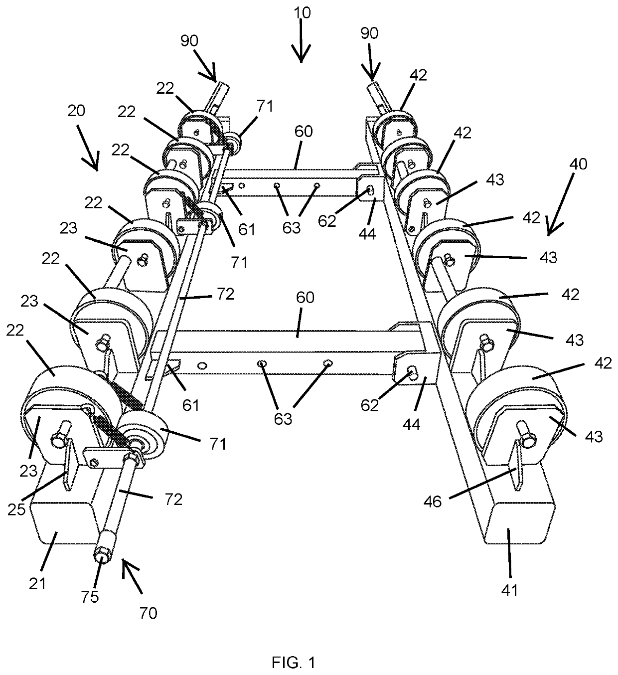
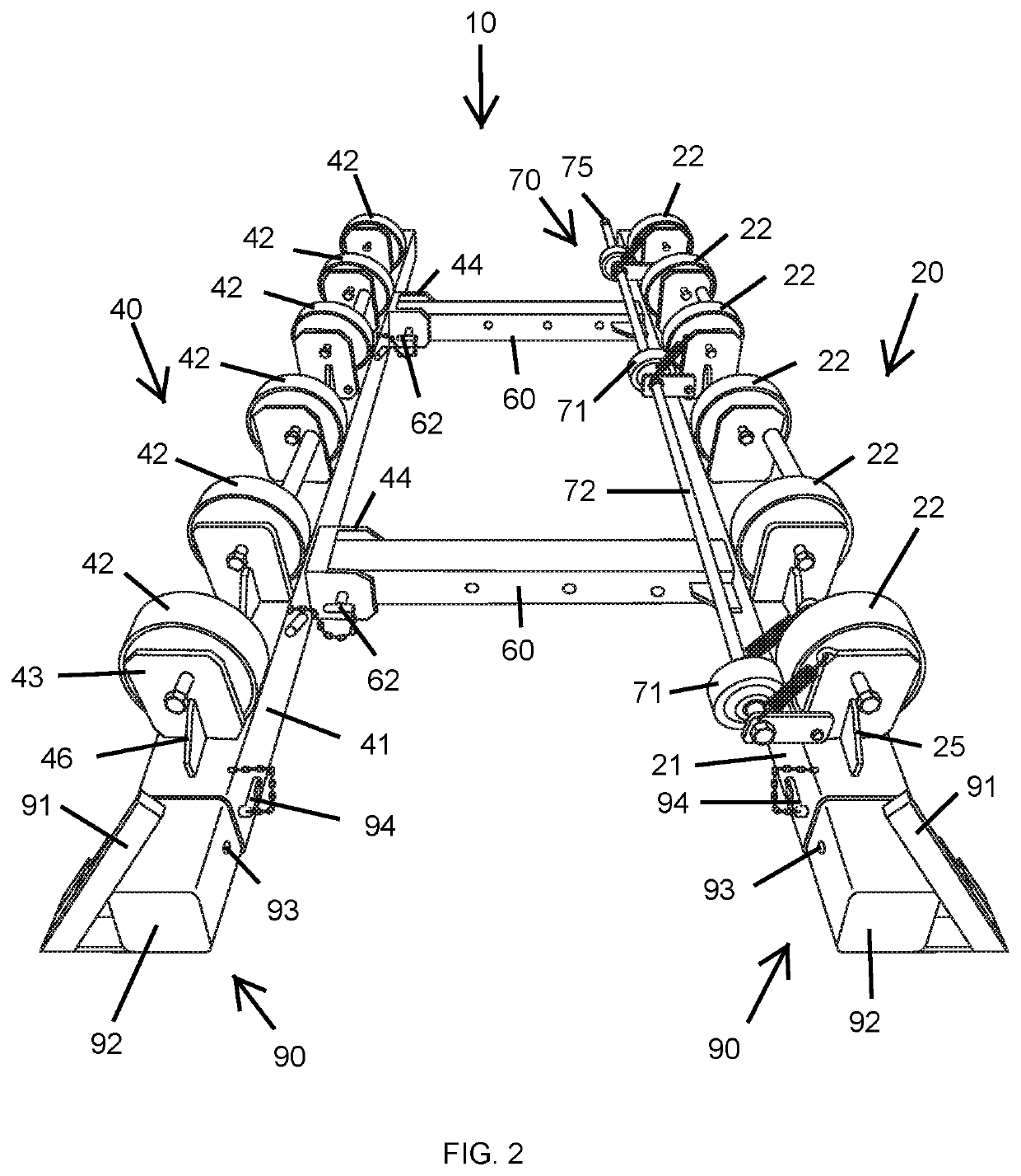
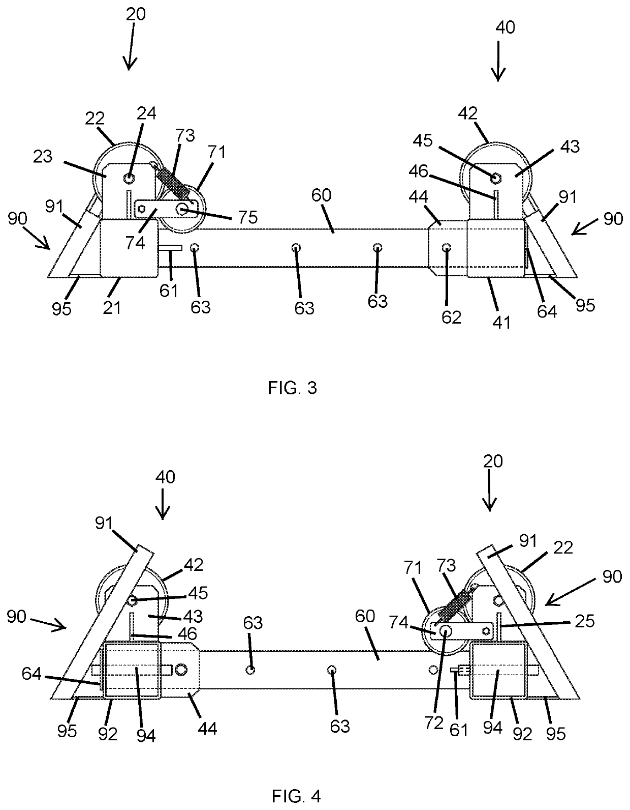
The present invention provides an adjustable workpiece positioning device for positioning and rotating cylindrical objects, such as pipes, during cutting, grinding, or machining. The device is easy to transport, set up, and adjust to accommodate different size objects. The device includes a fixed member and a movable member with rollers to support the object, and a means to move the movable member to support objects of various diameters. The device also includes a drive unit to rotate the object while on the rollers. The technical effect of this invention is to provide a versatile and easy-to-use tool for positioning and rotating cylindrical objects during machining processes.

Problems solved by technology

The present known devices which are designed to handle such pipes are permanently fixed and typically have a bulky motor drive which involves connection to three phase power within a workshop.
They are not designed to be portable and used at a worksite.
This also means that the user must assemble the manufactured work pieces always in the same work area; in fact it is very difficult and anti-economical to move the positioners to another work area within a same factory, or directly in a building yard, as this could require the displacement of a whole work line.
Positioning and perfect alignment of the circular sections is made difficult involving the use of conventional systems such as wedges, cranes and chains.
These devices are time consuming to set up and must be synchronized to operate together to ensure the workpiece is moved at the same time as it is turned or rotated.

Method used


Image

  • Work supporting and rotating apparatus
  • Work supporting and rotating apparatus
  • Work supporting and rotating apparatus

Examples


Embodiment Construction

[0056]The following description, given by way of example only, is described in order to provide a more precise understanding of the subject matter of a preferred embodiment or embodiments.

[0057]While the workpiece of the present invention will be described with regards to a concrete pipe, it should be appreciated by the person skilled in the art that other workpieces are not excluded by the present invention. For example the following invention can also be used to support and rotate such workpieces as steel pipes, ceramic pipes, glass pipes, fiberglass pipes, many metal pipes and plastic pipes.

[0058]For convenience in this specification, a cylindrical object to be supported and rotated will be, called a “workpiece” and the roller apparatus as a whole will be called a “rotator” which is a name by which such apparatus, for large-size workpieces, is known.

[0059]The present invention provides a portable work supporting and rotating apparatus to support and rotate pipe sections or other ...


PUM


Abstract

This invention relates in general to a portable work supporting and rotating apparatus for rotatable support of elongate workpieces of various diameters to be worked. The device having a longitudinally extending base frame with a fixed member and a movable member being disposed in generally parallel and spaced relation. A plurality of rollers are journaled on the fixed and movable members to rotatably support the elongated workpieces axially parallel to said rollers between the fixed and movable members. A means for moving the movable member in a transverse relationship with the fixed member is provided to increase or decrease a space between the fixed and movable members. A drive unit is operatively connected to one of the plurality of rollers permitting the workpiece to be rotated about a longitudinal axis.

Description

FIELD OF THE INVENTION[0001]This invention relates in general to a portable work supporting and rotating apparatus. In particular, the invention relates to an apparatus adapted to support and rotate pipe sections or other elongated generally cylindrical objects during cutting, grinding, machining or similar work of the pipes.BACKGROUND OF THE INVENTION[0002]It should be noted that reference to the prior art herein is not to be taken as an acknowledgement that such prior art constitutes common general knowledge in the art.[0003]A pipe is a tubular section or hollow cylinder, usually but not necessarily of circular cross-section, used mainly to convey substances which can flow, such as liquids and gases (fluids), slurries, powders and masses of small solids. Typically a pipe implies a level of rigidity and permanence, and can made out of many types of material including ceramic, glass, fiberglass, many metals, concrete and plastic. Concrete pipe in particular is utilised for low-press...

Claims


Application Information

Patent Timeline
IPC IPC(8): B23Q1/76B23K37/053B24B41/06
CPCB23Q1/763B24B41/067B23K37/0538B24B41/06F16L9/00B25H1/00
Inventor DALY, DAVID
Owner DALMAC ENTERPRISES PTY LTD
Learn More