Control System for a Valve

a control system and valve technology, applied in the direction of machines/engines, electric control of exhaust treatment, instruments, etc., can solve the problems of increasing emissions and fuel consumption, creating backpressure to the engine, negatively affecting engine performance, etc., to minimize back pressure to the engine, reduce the noise of exhaust, and improve the effect of exhaust nois

Active Publication Date: 2021-01-14
IVEX PTY LTD
View PDF0 Cites 1 Cited by
  • Summary
  • Abstract
  • Description
  • Claims
  • Application Information

AI Technical Summary

Benefits of technology

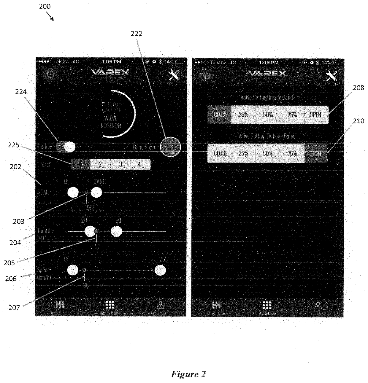
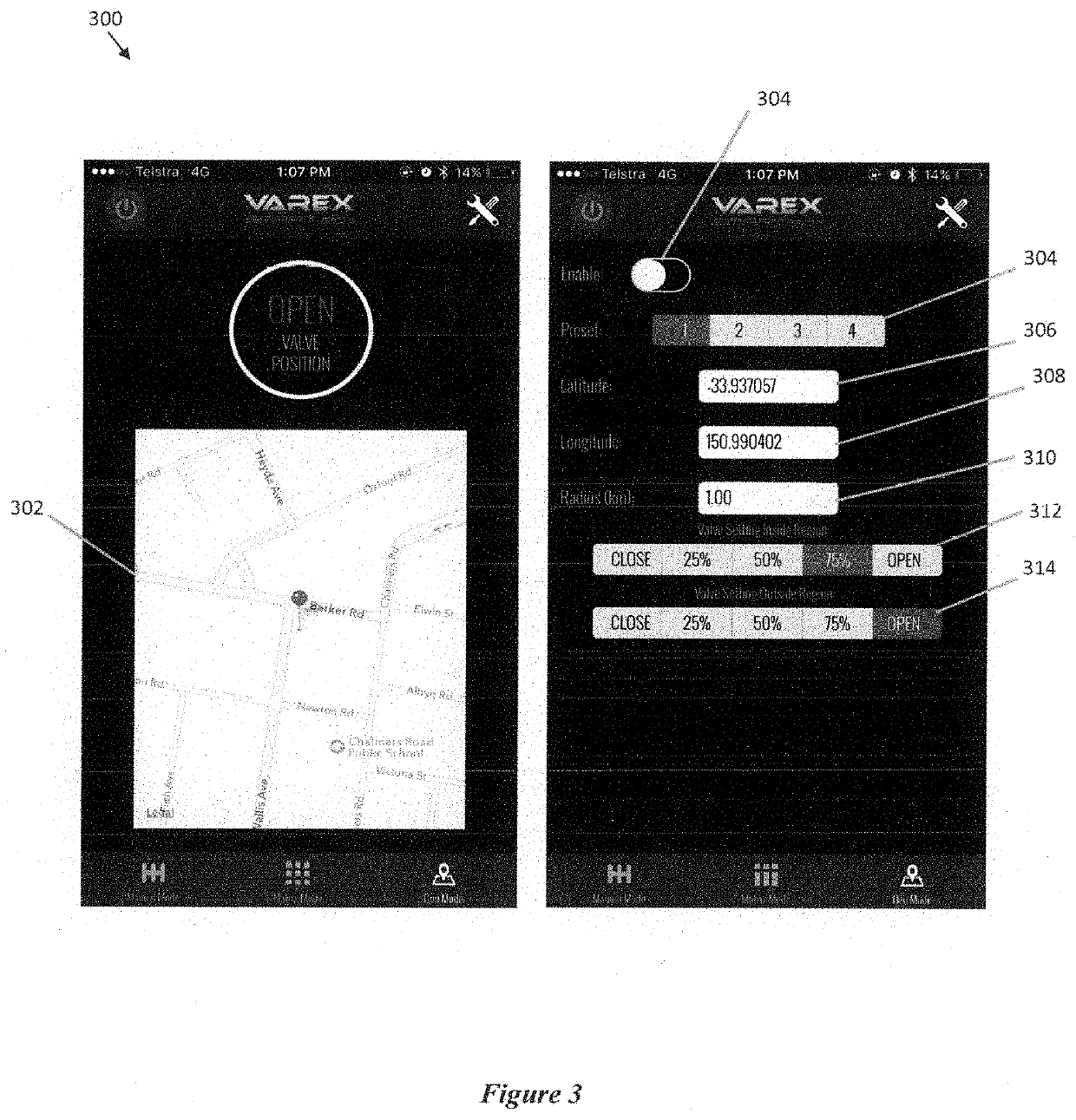
The control system described in this patent allows users to easily set the valve to any desired position during operation of the vehicle. This is particularly useful for driving in different locations and driving modes, as it ensures that the valve is set to provide optimal noise reduction and minimize back pressure to the engine. The system also allows users to fine tune the value range of each operating parameter through a visual interface and provides a GPS device on board the control circuit module for accurate location tracking. Overall, this patent improves the user experience and performance of the control system for vehicles.

Problems solved by technology

Whilst mufflers can reduce noise emissions by redirecting exhaust gasses from the engine, they can also create backpressure to the engine.
This can undesirably lead to an increase in emissions and fuel consumption, and can negatively impact engine performance.

Method used


Image

  • Control System for a Valve
  • Control System for a Valve
  • Control System for a Valve

Examples


Embodiment Construction

[0038]Certain terminology is used in the following description for convenience only and is not limiting. Unless specifically set forth herein, the terms “a”, “an” and “the” are not limited to one element but instead should be read as meaning “at least one”. The words “right,”“left,”“lower,” and “upper” designate directions in the drawings to which reference is made. The words “inwardly” or “distally” and “outwardly” or “proximally” refer to directions toward and away from, respectively, the geometric center or orientation of the device and instruments and related parts thereof. The terminology includes the above-listed words, derivatives thereof and words of similar import.

[0039]It should also be understood that the terms “about,”“approximately,”“generally,”“substantially” and like terms, used herein when referring to a dimension or characteristic of a component of the invention, indicate that the described dimension / characteristic is not a strict boundary or parameter and does not ...


PUM


Abstract

The preferred invention is directed to a controller for a vehicle exhaust valve. The controller comprises a vehicle interface for determining a live value for an operating parameter of a vehicle, a recording module being configured to, upon activation, instantaneously record the live value of the operating parameter, and a programming module for determining a value range based on the recorded live value and allowing a desired position of the valve to be set such that during operation, the control system automatically moves the valve to the desired position when the operating parameter is within the value range.

Description

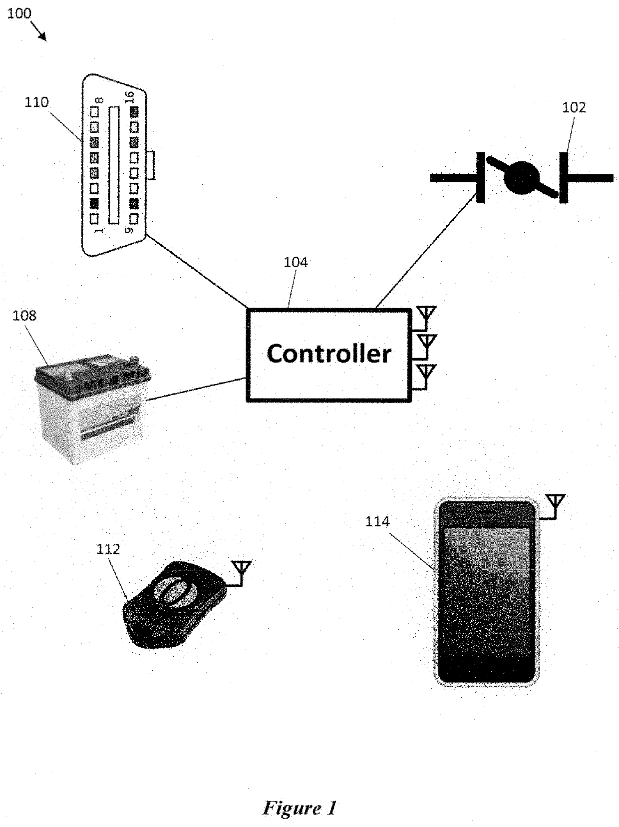
CROSS-REFERENCE TO RELATED APPLICATIONS[0001]The present application is a Section 371 of International Patent Application No. PCT / AU2017 / 050486, filed May 24, 2017 and entitled “Control System for a Valve” and claims the benefit of Australian Patent Application No. 2016902017, filed on May 27, 2016 and titled “Control System for a Valve,” the entire contents of which are incorporated herein by reference in their entirety.BACKGROUND OF THE INVENTION[0002]The invention described herein relates to a control system for a valve. In particular, embodiments of the invention are directed to a control system for a vehicle muffler exhaust valve.[0003]Mufflers can be used to reduce noise emissions from vehicle exhaust systems by providing a series of perforated conduits which work together to provide deconstructive interference of sound waves. An improved muffler assembly is described in Australian Patent No. 2007283449, the entire contents of which are incorporated herein by reference.[0004]W...

Claims


Application Information

Patent Timeline
IPC IPC(8): F01N1/16F02D9/04G07C5/08G01S19/42G07C5/00F01N9/00
CPCF01N1/165F02D9/04G07C5/085G07C5/0825G01S19/42G07C5/0808F01N2900/08F01N9/00F02D2200/101F02D2200/501F02D2200/701F01N2900/10G07C5/006F02D9/08F01N1/163F01N1/166F01N1/168F01N2900/0411F01N2900/0412F01N2900/12
Inventor FENGKOVAC, JESSE
Owner IVEX PTY LTD
Why Eureka
Try Eureka