Stereoscopic image display device and stereoscopic image display method

a stereoscopic image and display device technology, applied in the field of stereoscopic image display devices and stereoscopic image display methods, can solve the problems of deteriorating the resolution and brightness of the reproduced stereoscopic image, the image display switching speed of the image display panel is limited, and the structure is complicated, so as to increase the density of light rays, reduce the display area, and the effect of high speed

Active Publication Date: 2021-01-07
ASUKANET
View PDF2 Cites 0 Cited by
  • Summary
  • Abstract
  • Description
  • Claims
  • Application Information

AI Technical Summary

Benefits of technology

This patent describes a new stereoscopic image display device and method that allows for a more compact and high-resolution display by dividing the screen into multiple sections and displaying small images in each section. The small images are composed of a plurality of minute images arranged in a dispersion state, which increases the density of the light rays forming a three-dimensional image. The device can switch between the small images quickly to provide a clear three-dimensional image. The method also allows for the efficient extraction of light rays from each small image by time-dividing the display ranges of the sections. The resulting image is a clear and high-definition three-dimensional image with minimal distortion. The device and method can be used in both displaying a moving image and providing an afterimage retention time for the viewer's eye. Overall, this new technology provides a more immersive and reconfigurable experience for viewers.

Problems solved by technology

Also, if the pitch of the pinholes is wider, the small images become sparser which deteriorates the resolution and brightness of the reproduced stereoscopic image.
However, if the pitch of the pinholes becomes too narrow, the displaying areas of the adjacent small images overlap with each other.
Nevertheless, the image display switching speed of the image display panels has a limitation.
Thus, the following problems arise.
For the stereoscopic image display device as set forth in patent literature 1, the structure is complicated and the back side of the display control panel grows in size.
Therefore, there is a problem that spatial and temporal constraints occur with regard to using (utilizing) the devices.

Method used


Image

  • Stereoscopic image display device and stereoscopic image display method
  • Stereoscopic image display device and stereoscopic image display method
  • Stereoscopic image display device and stereoscopic image display method

Examples


Embodiment Construction

[0050]An embodiment of the present invention will be described next with reference to the accompanying drawings to provide an understanding of the present invention.

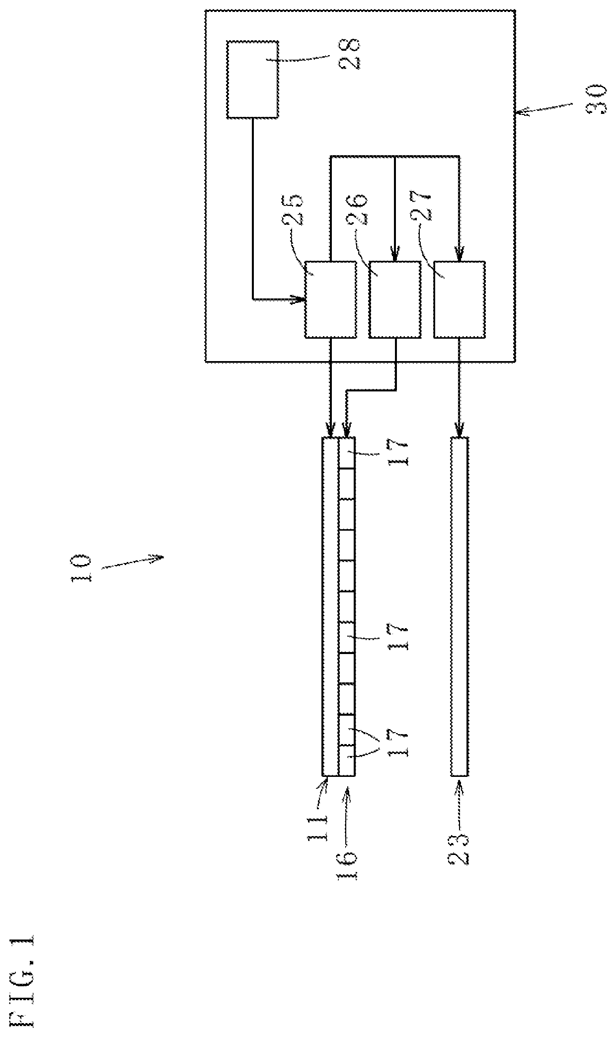
[0051]A stereoscopic image display device 10 according to the embodiment of the present invention shown in FIGS. 1 to 6(D) forms a three-dimensional image (stereoscopic image) by converging light rays output from a plurality of small images 12a to 12d displayed on a display 11.

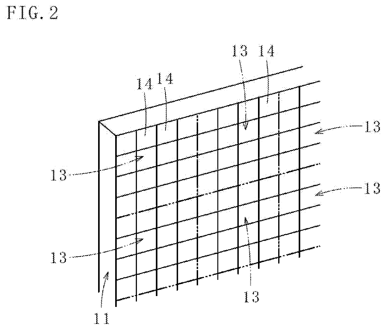
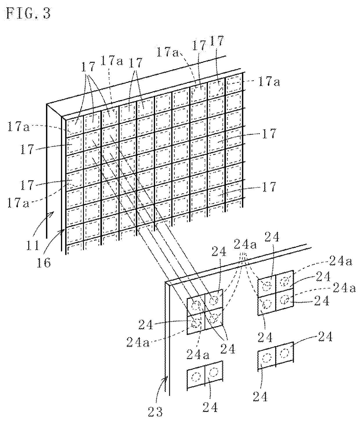
[0052]As shown in FIG. 2, the displaying surface of the display 11 is divided into a plurality of sections 13. Although each section 13 is an area that includes four pixels in height by four pixels in width in this embodiment, the number of the pixels composing each section can be selected as appropriate. Note that each section 13 here represents a displaying area on the display 11 and it does not mean that the display 11 is physically divided. In each section 13, as shown in FIGS. 4(A) to 5, the small images 12a to 12d each including a plurality (...


PUM


Abstract

A stereoscopic image display device includes a display 11 divided into sections 13 in each of which displayed are small images 12a to 12d each having a plurality of minute images 14, a shutter panel 16 disposed in front of the display 11 and including first mechanical shutters 17, which are arranged side by side in units of the minute image 14 and time-divisionally divide each section 13 per each of the small images 12a to 12d by switching on and off in units of the minute image 14, and an image forming panel 23 including image forming means 24 arranged side by side for forming an image from light rays from each of the small images 12a to 12d passing through the first mechanical shutters 17 when the first mechanical shutters 17 are on.

Description

TECHNICAL FIELD[0001]The present invention is related to a stereoscopic image display device and a stereoscopic image display method that enable a high-definition stereoscopic image (including a two-dimensional image) to be viewed with a similar feeling to everyday life without any use of special glasses.BACKGROUND ART[0002]Among various stereoscopic image display methods, the spatial image reproduction system, in which a stereoscopic image is formed in the air by using recorded data (images) of an optical spatial image of an object, has been conventionally deemed to be an ideal stereoscopic image display method.[0003]The principle of the spatial image reproduction system is explained below. As shown in FIG. 10, a light-blocking panel 51 is disposed in front of a three-dimensional object (an object) 50 with a predetermined space therebetween. The light-blocking panel 51 is provided with a plurality (three, in this explanation) of pinholes 52a to 52c formed. Further in front of the l...

Claims


Application Information

Patent Timeline
IPC IPC(8): G02B30/24
CPCG02B30/24H04N13/302G03B35/16H04N13/315G02B30/31H04N13/354H04N13/398
Inventor OTSUBO, MAKOTO
Owner ASUKANET
Why Eureka
Try Eureka