
Hydraulic steering systems for vehicle wheels

a steering system and hydraulic technology, applied in fluid steering, lifting devices, vehicle components, etc., can solve the problems of hydraulic sealing failure, cylinder seal strain, and the direction of the force vector acting through the steering lever

Active Publication Date: 2021-01-07
COMBIELEVATOR
View PDF0 Cites 2 Cited by
  • Summary
  • Abstract
  • Description
  • Claims
  • Application Information

AI Technical Summary

Benefits of technology

The patent describes a way to connect the hydraulic cylinders in a steering system of a vehicle to the wheel carrier. By using a pivotally mounted hydraulic cylinder with a rigid connecting rod assembly that extends directly to the pivot point on the wheel carrier, the hydraulic cylinder can change its orientation to accommodate the angular change in position of the pivot point on the wheel carrier. This helps to minimize the lateral buckling forces, which can cause damage to the seals of the cylinder. The design also allows for a larger range of steering angles by allowing the pivot point to be driven“around” a part of the wheel carrier.

Problems solved by technology

A drawback with such a system is that the force vector acting through the steering lever varies in direction throughout the range of steering angles.
This places a strain on the cylinder seals and may lead to a failure of the hydraulic sealing.
Rigid hydraulic lines are more expensive to make, more expensive to replace, and can be less reliable especially on mobile equipment due to vibration.

Method used


Image

  • Hydraulic steering systems for vehicle wheels
  • Hydraulic steering systems for vehicle wheels
  • Hydraulic steering systems for vehicle wheels

Examples


Embodiment Construction

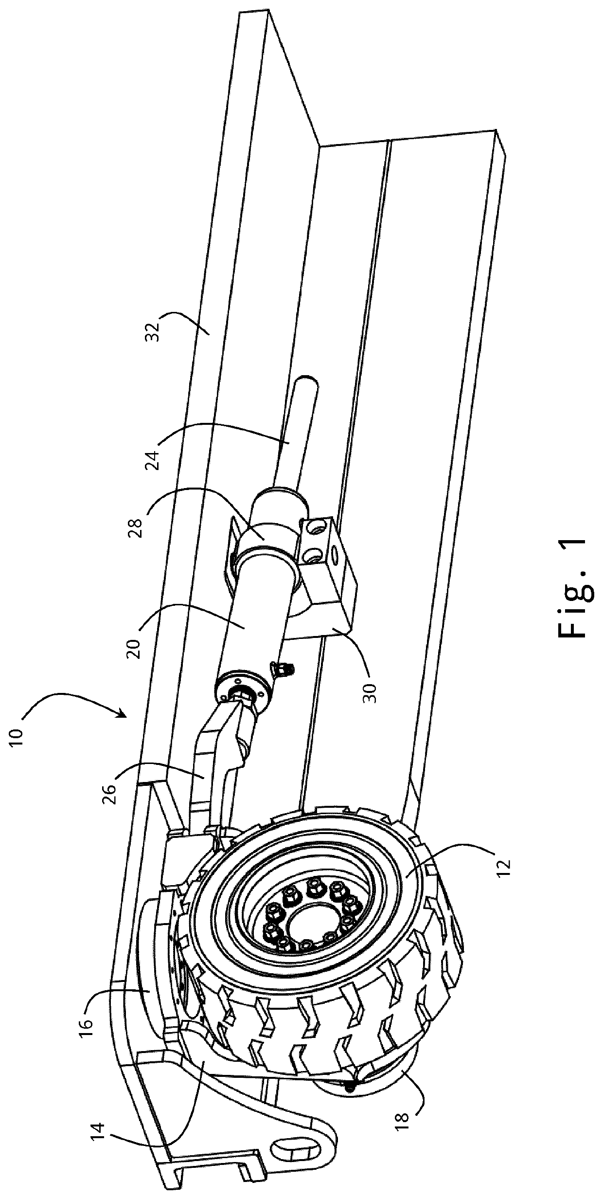
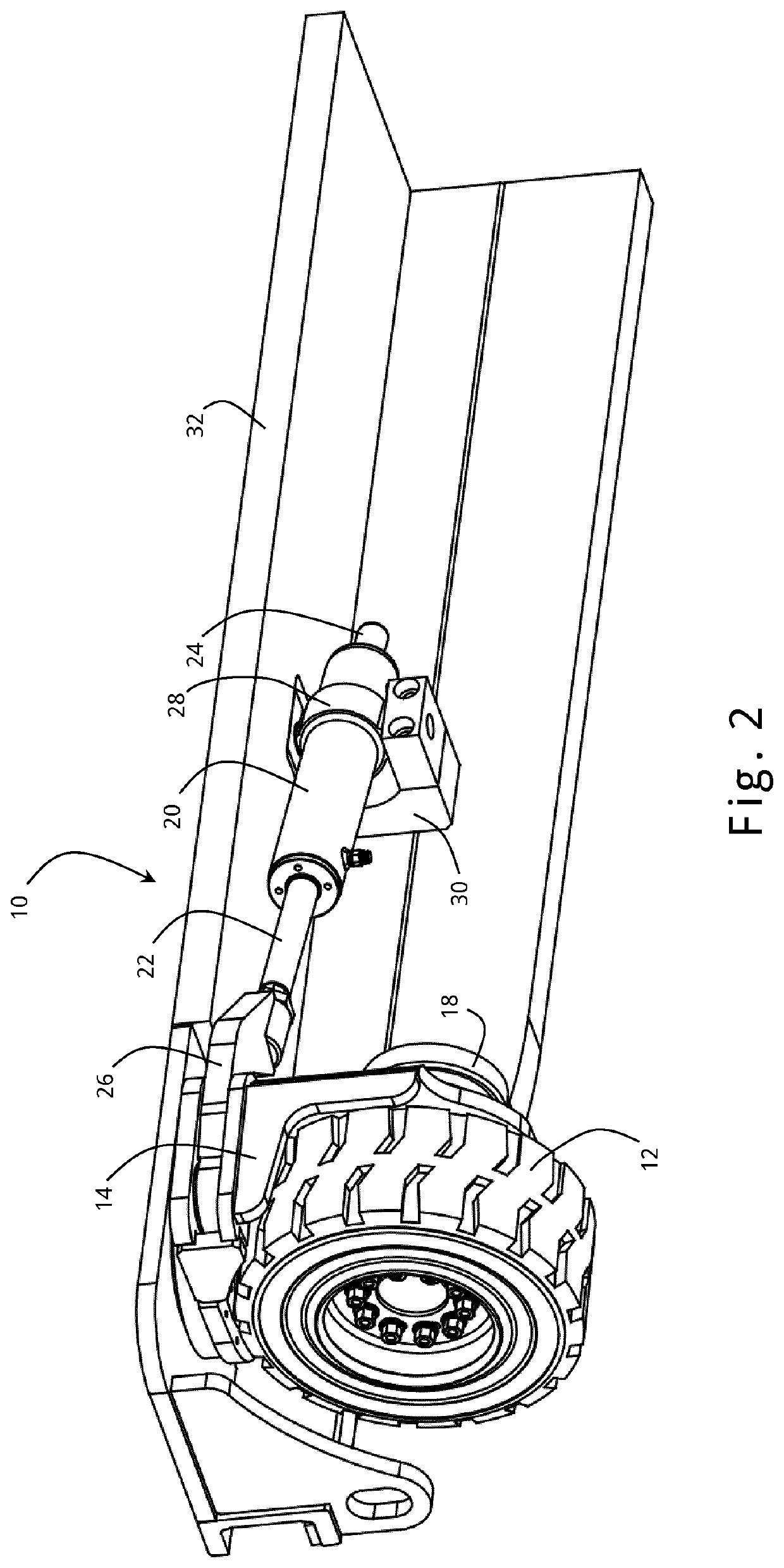
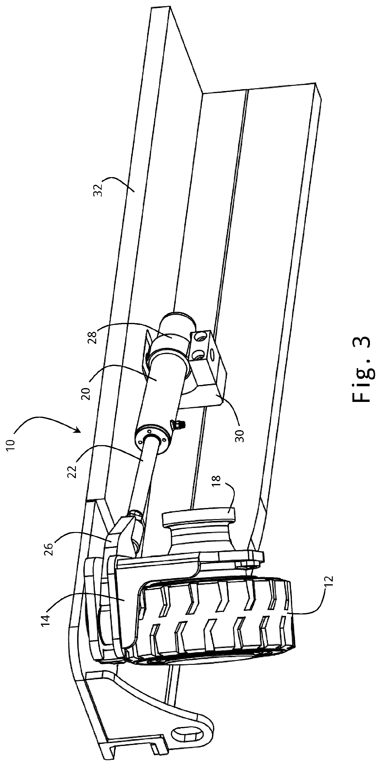
[0035]Referring to FIGS. 1-3, a steering system 10 for a vehicle wheel 12 is shown in perspective view.

[0036]FIG. 1 shows the system when the wheel 12 is steered straight ahead. FIG. 2 shows the system when the wheel 12 is steered at right angles, i.e. having been turned 90° to steer in a sideward direction. FIG. 3 shows the system when the wheel 12 is steered to its maximum extent, beyond 90°, to a steering angle of approximately 135°.

[0037]The wheel 12 is mounted on a wheel carrier 14 which in turn is mounted on a bearing or hub 16 which permits the wheel to be rotated about a vertical axis relative to the chassis 32 of a vehicle. A drive motor 18, which may for example be hydraulic or electric, is mounted on the wheel 12 permitting the wheel to be driven in a forward or a reverse direction. It will be appreciated that the nature of the vehicle drive system, and the coupling of the drive system to the wheel, is not essential to the steering system and can be varied according to th...


PUM


Abstract

A steering system (10) for a vehicle wheel (12) has a wheel carrier (14) for mounting a steered wheel (12), the wheel carrier (14) being rotatably mounted with respect to the vehicle about a steering axis to allow the wheel (12) to be steered. A hydraulic cylinder (20) has a piston therein and a rigid connecting rod assembly (22) extending from the piston out of the cylinder (20). The rigid connecting rod assembly (22) comprises a first section (22) adapted to reciprocate into and out of the cylinder (20) and a second section (26) rigidly extending from the first section (22) to a pivot point connection (50) where it is pivotally connected to the wheel carrier (14) at an offset from the steering axis. The hydraulic cylinder (20) is pivotally mounted on the vehicle such that it is prevented from translational movement relative to the vehicle but capable of changing its orientation with respect to the vehicle. Due to the rigid connecting rod assembly (22) and the pivot connection to the wheel carrier (14), as well as the pivotal mounting of the cylinder (20) on the vehicle, lateral strains on the seals of the hydraulic cylinder (20) are avoided.

Description

TECHNICAL FIELD[0001]This invention relates to hydraulic steering systems for vehicle wheels, and to vehicles equipped with such systems.BACKGROUND ART[0002]Hydraulic steering systems are commonly used in vehicles such as forklift trucks. Typically, a hydraulic cylinder controls the rotation of a wheel carrier about a generally vertical steering axis. The extension or retraction of the cylinder's connecting rod pushes or pulls an offset point on the wheel carrier and causes the carrier to rotate about the steering axis, thereby steering a wheel mounted on the carrier.[0003]An example of such a steering system is disclosed in WO 2014 / 075921. A pair of steerable wheels are disclosed, each controlled by a hydraulic cylinder, with the cylinders being connected in series such that they operate in synchronicity on their respective wheels. Each hydraulic cylinder is immovably mounted to the vehicle chassis and has an active connecting rod that is capable of reciprocating movement in conven...

Claims


Application Information

Patent Timeline
Patent Type & Authority Applications(United States)
IPC IPC(8): B62D5/12B62D7/02B62D7/15
CPCB62D5/12B62D7/026B66F9/07559B62D7/1536B62D7/1509B66F9/07568B62D7/02B62D5/26
Inventor MCVICAR, MARTINMOFFETT, ROBERTWHYTE, MARK
Owner COMBIELEVATOR
Learn More