
Method of carrying out thermolysis and thermolysis apparatus

a technology of thermolysis and apparatus, which is applied in the direction of mechanical conveying coke ovens, products, educts, etc., can solve the problems of inability to achieve the high temperature needed in thermolysis in a techno-economically feasible way, small opening area of feeding zone, and difficulty in effective heating, etc., to achieve the effect of reducing the volume of the feeding material, reducing the difficulty of feeding, and increasing the difficulty of feeding

Pending Publication Date: 2020-12-24
TEKNOLOGIAN TUTKIMUSKESKUS VTT
View PDF1 Cites 1 Cited by
  • Summary
  • Abstract
  • Description
  • Claims
  • Application Information

AI Technical Summary

Benefits of technology

The patent describes a method and apparatus for processing low bulk weight feed materials, such as plastics and biobased materials, through heating. The process is efficient, economical, and can handle more challenging materials without the need for pre-compacting. The large area for heat transfer allows for faster and more controlled tempering, reducing the risk of charring or local over-heating. The extruder design also facilitates more precise mixing and control of pressure gradient, which can improve the removal of volatile compounds and enable the use of halogenated plastics as feeding materials. Additionally, the use of paper, cardboard, and cellulose fiber containing polymer composites as extruder feeding materials can increase the recycling flow compared to restricting plastics.

Problems solved by technology

The main challenge in the existing methods and apparatuses is a relatively small feeding zone opening area compared to volume flow and the challenges in effective heating of thermolysing material in conventional one screw extruders.
Relatively small feeding zone opening area restricts the use of bigger dimension and fluffy feeding material in conventional extruders.
The challenges of effective heating of materials in thermolysis temperatures with conventional extruders are due to physical phenomena where the major of heating energy input is gained through the inner friction / viscosity of the processed material.
However, as the temperature rises the inner friction / viscosity lowers and high temperatures needed in thermolysis cannot be reached in a techno-economically feasible way.

Method used


Image

  • Method of carrying out thermolysis and thermolysis apparatus
  • Method of carrying out thermolysis and thermolysis apparatus
  • Method of carrying out thermolysis and thermolysis apparatus

Examples


Embodiment Construction

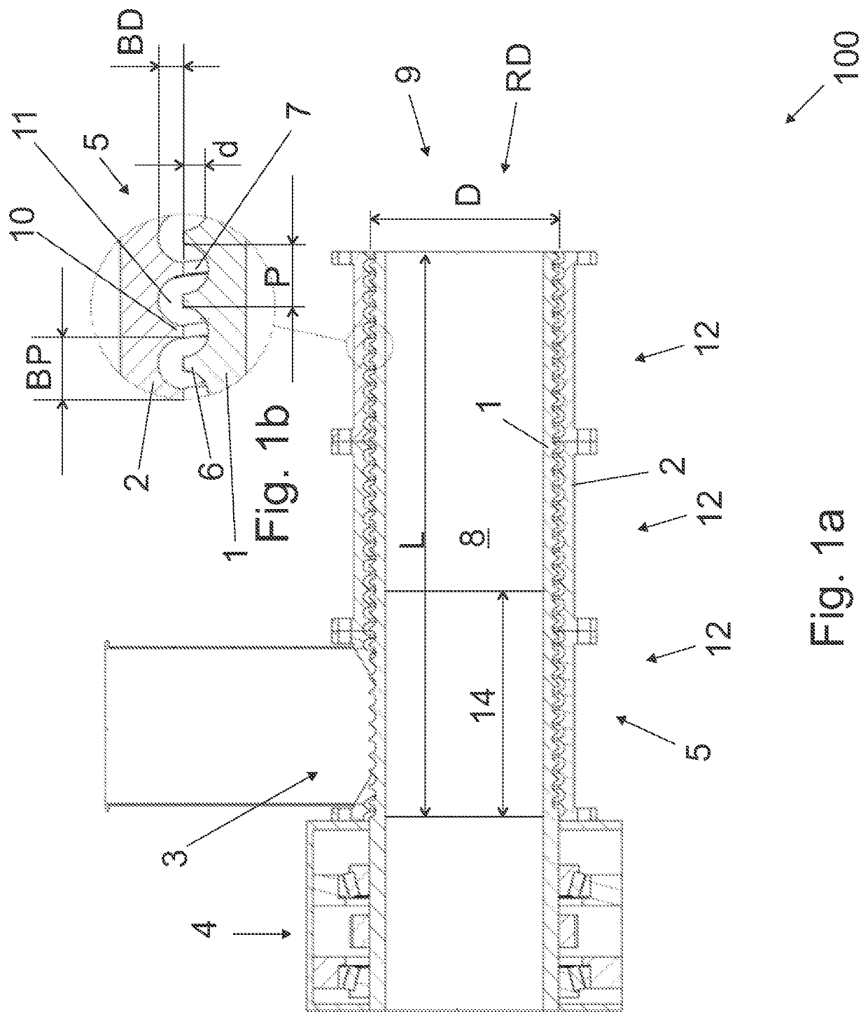
[0040]FIG. 1a is a schematic side view of an apparatus in partial cross-section, and FIG. 1b is a schematic view of a detail of the apparatus shown in FIG. 1a in partial cross-section.

[0041]The apparatus is a single-screw extruder 100. The extruder 100 is preferably capable to process any kind of organic material (material hereafter) to be thermolysed, and it may also be used as pre-thermolyser. The form of the material does change when passing through the extruder, i.e. material or mixture of materials may, for instance, compress, compact, consolidate, grind, break apart, melt, react, decompose, and / or degrade.

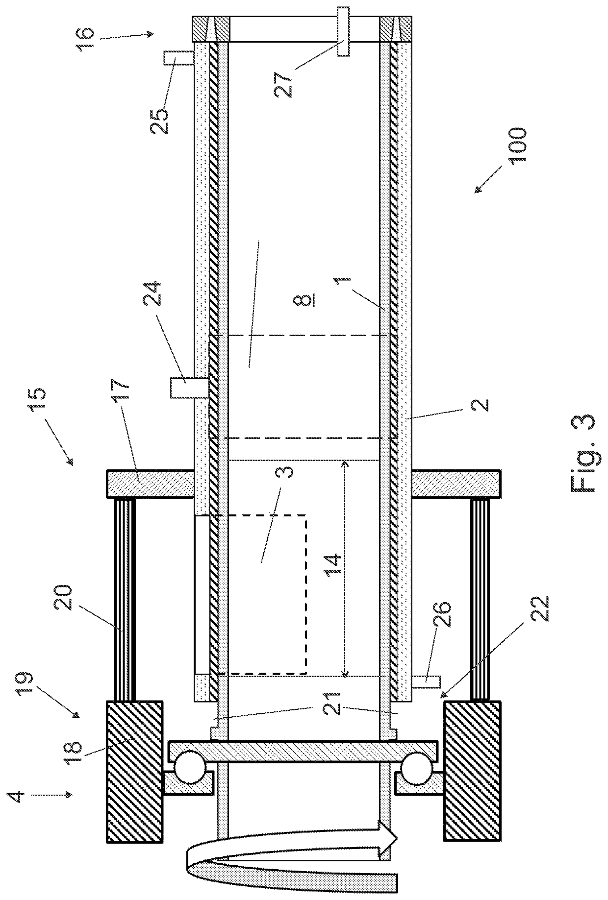
[0042]The extruder 100 is a single-screw extruder comprising a cylindrical rotor member 1, a barrel 2, a feed opening 3, and a drive system 4 for the rotation of the rotor member 1 in the barrel 2.

[0043]The rotor member 1 has diameter D and length L. In an embodiment, the relation of the length to the diameter, i.e. L:D, is in range of 2:1 to 4:1.

[0044]The cylindrical outer s...


PUM

PropertyMeasurementUnit
temperatureaaaaaaaaaa
diameteraaaaaaaaaa
lengthaaaaaaaaaa

Abstract

A method and apparatus for thermolysing organic material. The method comprises steps of: A) feeding the material in a single-screw extruder (100), the extruder comprising —a cylindrical rotor member (1) having diameter (D) and length (L) and comprising a feeding zone (14), —the rotor member (1) arranged in a barrel (2), —the cylindrical surface of the rotor member (1) carrying cavity / cavities and / or projection(s) (5) arranged in helically extending rows, —the helically extending row(s) of the rotor member (1) having a pitch (P) and depth (d) in the feeding zone (14) of the rotor member, wherein —the relation of the depth (d) to the diameter (D) of the rotor member, i.e. d:D, is not more than 1:20, and —the relation of the pitch (P) of the rotor member to the diameter (D) of the rotor member, i.e. P:D, is not more than 1:4, B) heating the material in the single-screw extruder (100) to a flowable state, and C) thermolysing the material.

Description

BACKGROUND[0001]The invention relates to a method for thermolysing organic material.[0002]The invention further relates to a thermolysing apparatus.[0003]It is known to use extruders in heating / melting material to be processed. The main challenge in the existing methods and apparatuses is a relatively small feeding zone opening area compared to volume flow and the challenges in effective heating of thermolysing material in conventional one screw extruders. Relatively small feeding zone opening area restricts the use of bigger dimension and fluffy feeding material in conventional extruders.[0004]The challenges of effective heating of materials in thermolysis temperatures with conventional extruders are due to physical phenomena where the major of heating energy input is gained through the inner friction / viscosity of the processed material. However, as the temperature rises the inner friction / viscosity lowers and high temperatures needed in thermolysis cannot be reached in a techno-ec...

Claims


Application Information

Patent Timeline
Patent Type & Authority Applications(United States)
IPC IPC(8): B29C48/68B29C48/59B29B7/42B29B7/72B29B7/82C10B47/44C10B53/07C10B7/10
CPCB29B7/72B29B7/425B29C48/681B29B7/92C10B47/44B29B7/422C10B53/07C10B7/10B29B7/826B29C48/59Y02P20/143B29C48/397B29C48/505B29C48/501B29C48/688B29C45/60C10B47/32C10B49/00C10B1/06
Inventor OASMAA, ANJAMINKKINEN, HANNULINDFORS, CHRISTIANLEHTO, JANIMANNILA, JUHA
Owner TEKNOLOGIAN TUTKIMUSKESKUS VTT
Learn More